
Integrated low power digital gyro control electronics

Active Publication Date: 2005-07-05
CALIFORNIA INST OF TECH +2
View PDF27 Cites 38 Cited by
  • Summary
  • Abstract
  • Description
  • Claims
  • Application Information

AI Technical Summary

Benefits of technology

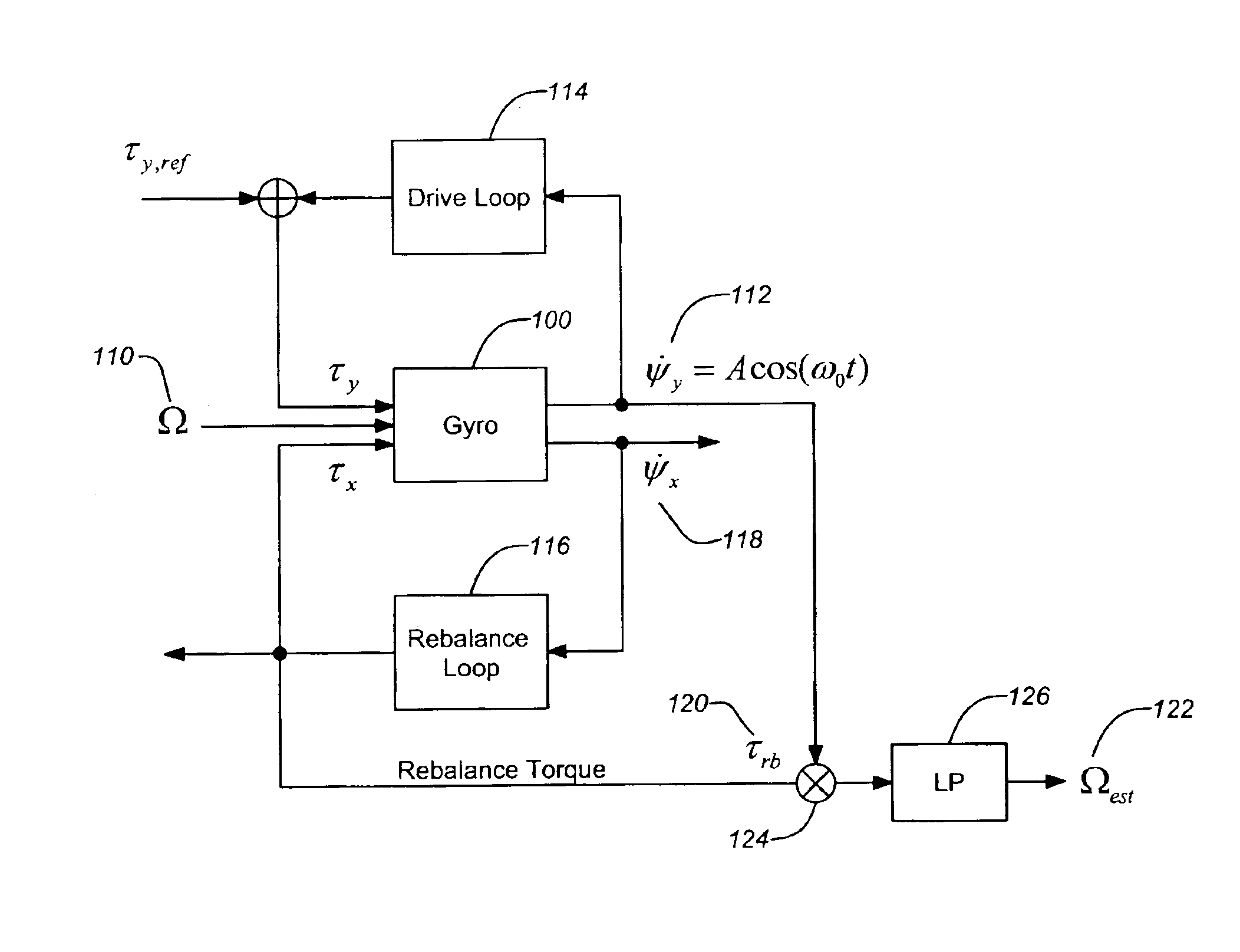
[0014]In order to accommodate gyroscope variability, the digital drive control circuit and the digital rebalance controller circuit are programmable such that the circuit device can be matched to a particular vibratory gyroscope. For example, the digital drive control circuit and the digital rebalance controller circuit can each include one or more programmable finite impulse response (FIR) filters programmed to match the particular vibratory gyroscope. In addition, the programmable digital drive control circuit and the programmable digital rebalance controller circuit can include one or more programmable amplifiers, such as those used at the input and / or output of the drive circuit and rebalance circuit to isolate the drive and sense modes of the gyroscope. Alternately, a programmable filter architecture can be employed to aid in isolating the drive and sense modes.

Problems solved by technology

The disadvantage of a discrete analog implementation is its inflexibility with regard to modifying component values for the purpose of “tuning” or customizing the control loops for a given sensor.
Since mass-produced sensors will have some degree of variability amongst a batch of supposedly identical devices, this inflexibility represents a significant drawback.
On the other hand, one disadvantage of using a general purpose digital signal processing chip is that general purpose centralized DSPs do not lend themselves to applications in which low power consumption is necessary (e.g., spacecraft, mobile systems, etc.).

Method used


Image

  • Integrated low power digital gyro control electronics
  • Integrated low power digital gyro control electronics
  • Integrated low power digital gyro control electronics

Examples


Embodiment Construction

[0031]In the following description of the preferred embodiment, reference is made to the accompanying drawings which form a part hereof, and in which is shown by way of illustration a specific embodiment in which the invention may be practiced. It is to be understood that other embodiments may be utilized and structural changes may be made without departing from the scope of the present invention.

1. Exemplary Gyroscope Model

[0032]As discussed above, vibratory rate gyroscopes exploit a Coriolis term in the equations of motion to link two modes of the sensor's elastic structure. One mode is driven to a constant-amplitude harmonic response (requiring a drive loop) and consequently any angular motion about the sensor's sensitive axis causes the other mode to respond to this rotation. The amplitude of this response is related to the angular rotation rate. A second feedback loop, the balance loop, is often used to regulate the response of the second mode to zero and in this case the feedb...


PUM


Abstract

Embodiments of the invention generally encompass a digital, application specific integrated circuit (ASIC) has been designed to perform excitation of a selected mode within a vibratory rate gyroscope, damping, or “force-rebalance,” of other modes within the sensor, and signal demodulation of the in-phase and quadrature components of the signal containing the angular rate information. The ASIC filters dedicated to each channel may be individually programmed to accommodate different rate sensor designs / technology or variations within the same class of sensors. The ASIC architecture employs a low-power design, making the ASIC, particularly suitable for use in power-sensitive applications.

Description

CROSS-REFERENCE TO RELATED APPLICATIONS[0001]This application claims the benefit under 35 U.S.C. §119(e) of the following U.S. patent application, which is incorporated by reference herein:[0002]U.S. Provisional Application Ser. No. 60 / 391,350, filed Jun. 25, 2002, by Robert M'Closkey et al., entitled “INTEGRATED LOW POWER DIGITAL GYRO CONTROL ELECTRONICS”.STATEMENT OF GOVERNMENT RIGHTS[0003]The invention described herein was made in the performance of work under a NASA contract and is subject to the provisions of Public Law 96-517 (35 U.S.C 202) in which the Contractor has elected to retain title.BACKGROUND OF THE INVENTION[0004]1. Field of the Invention[0005]The present invention relates to devices and methods of controlling and signal processing for vibratory gyroscopes.[0006]2. Description of the Related Art[0007]Vibratory rate gyroscopes exploit a coriolis term in the equations of motion to link two modes of the sensor's elastic structure. One mode is driven to a constant-ampli...

Claims


Application Information

Patent Timeline
IPC IPC(8): G01C19/56
CPCG01C19/56
Inventor M'CLOSKEY, ROBERTCHALLONER, A. DORIANGRAYVER, EUGENEHAYWORTH, KEN J.
Owner CALIFORNIA INST OF TECH
Learn More