
Bimetal acetabular component construct for hip joint prosthesis

a technology of acetabular components and hip joints, applied in the field of surgical equipment and procedures, can solve the problems of inability to use, abandonment, and inability to accept teflon “tmj” replacements, and achieve the effects of superior bone ingrowth, superior bone ingrowth, and superior polyethylene-engaging faces

Inactive Publication Date: 2005-05-12
HAYES JR DANIEL +1
View PDF63 Cites 36 Cited by
  • Summary
  • Abstract
  • Description
  • Claims
  • Application Information

AI Technical Summary

Benefits of technology

[0026] This invention provides for a novel orthopedic prosthesis, specifically a prosthetic acetabular component for a prosthetic total hip joint, that comprises two constructs, one being a metal base construct that engages the bone and the other being a polyethylene bearing construct that attaches to the metal base construct and articulates with a prosthetic hip component on the opposing side of the joint. The metal base construct is composed of two different metals, one of which engages the bone surface and the other of which engages the polyethylene bearing construct. Each of these metals is selected so that its characteristics are well suited to its particular function. More particularly, the first metal (i.e., the one that engages the bone surface) is selected so as to provide a superior bone-engaging face, while the second metal (i.e., the one that engages the polyethylene bearing construct) is selected so as to provide a superior polyethylene-engaging face. By combining the different material characteristics of two different metals in the metal base construct, it is possible to simultaneously form a superior bone-engaging face and a superiorpolyethylene-engaging face. Among other things, by selecting two appropriate metals for the metal base construct, superior bone ingrowth can be achieved while still avoiding the aforementioned problems with “backside wear”.

Problems solved by technology

Other attempts, such as acrylic femoral head replacements or Teflon “TMJ” replacements, were found to be unacceptable and have been abandoned.
Ceramic bearing couples have also been used in the art to some extent, but their use is relatively limited due to price and strength considerations.
Titanium alloys, however, also tend to suffer from notch sensitivity in fatigue, which significantly reduces the fatigue strength of the construct when the surface is notched, roughened or porous-coated.
Titanium alloys are also prone to scratching and make relatively poor sliding couples with polyethylene.
However, CoCr alloys are also relatively stiff, which can cause load pattern problems when coupled with flexible human bones, and they are not as biocompatible as many other alloys due to their chrome, and in some cases nickel, content.
However, the applications that included sliding surfaces, such as femoral heads for the hip and knee femoral components, tended to have significant problems with wear debris and scratching, and many exhibited clinical failure.
This layered construction is desirable because stems made entirely of titanium, with titanium ingrowth surfaces, are too weak, while stems that are made entirely of CoCr, with CoCr ingrowth surfaces, do not have adequate biocompatibility.
However, HA, while it yields excellent short term results, has problems with long term stability due to its pH sensitivity.
More particularly, the pH of the body may fluctuate due to a variety of conditions such as nutrition and disease, and this can undermine the effectiveness of HA bone ingrowth surface.
The main limitation to this approach is that loading and abrading tend to undermine the mechanical integrity of the union between the ceramic coating and the substrate, and this can lead to prosthesis failure.
As wear issues relating to the main articulating surfaces have been addressed and incidences of gross and catastrophic wear eliminated, it has been discovered that the locking interface between the polyethylene bearing construct and the metal base construct can also be a significant source of wear debris.
This issue of “backside wear” has been a significant issue for research and debate over the last five years or so.
Attempts to address this issue have, to date, been limited to polishing the titanium mating surface of the metal base construct, as disclosed in U.S. Pat. No. 5,310,408 and as practiced in the “Reflection Cup” product marketed by Smith+Nephew of Memphis, Tenn.
However, polishing a titanium surface has not worked well in previous attempts in sliding couples (i.e., in the femoral head component of a prosthetic total hip and in the prosthetic femoral component of a prosthetic total knee), and it has had only limited success in reducing wear debris at the locking interface between the polyethylene bearing construct and the metal base construct.
This is primarily due to the inherent material limitations of the titanium metal base construct in the polished locking mechanism configuration.
No existing bimetallic constructs lock with polyethylene.

Method used


Image

  • Bimetal acetabular component construct for hip joint prosthesis
  • Bimetal acetabular component construct for hip joint prosthesis
  • Bimetal acetabular component construct for hip joint prosthesis

Examples


Embodiment Construction

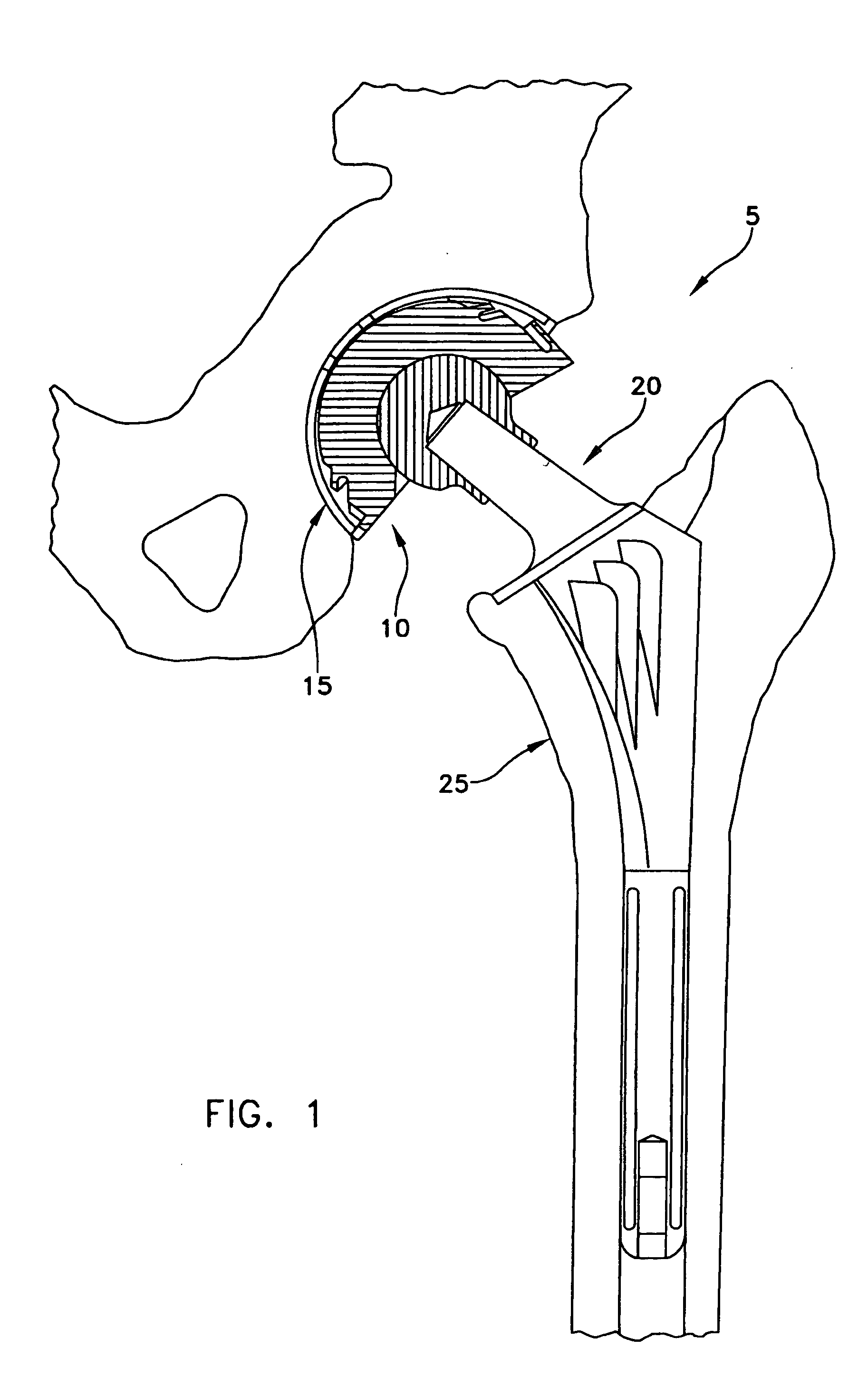
[0031] Looking first at FIG. 1, there is shown a prosthetic total hip joint 5 which generally comprises a prosthetic acetabular component 10 seated in a recess contained in a prepared hip 15, and a prosthetic femoral stem component 20 which is secured to the top end of a resected femur 25.

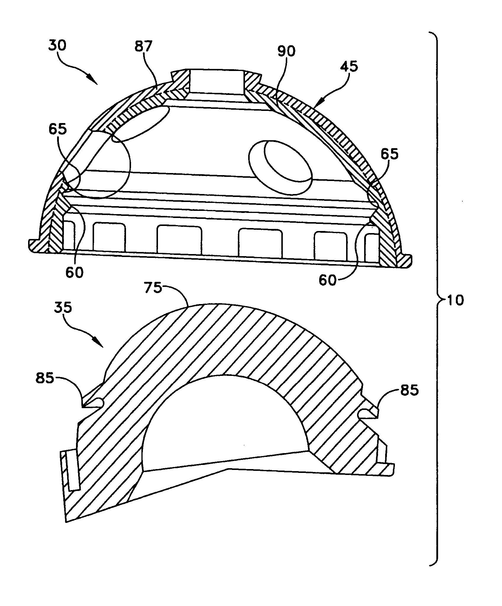
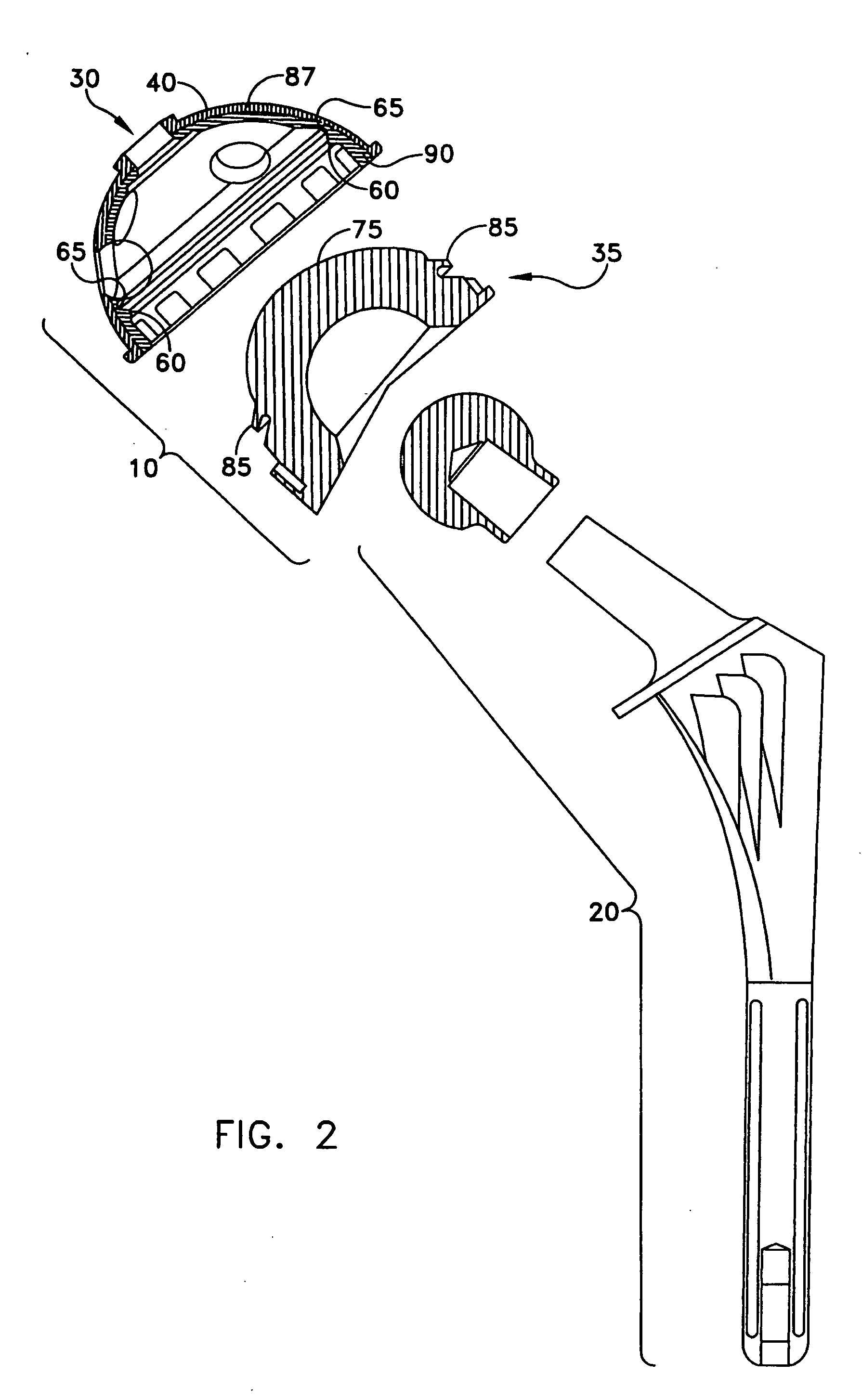
[0032] Prosthetic acetabular component 10 is shown in greater detail in FIGS. 2 and 3. Prosthetic acetabular component 10 generally comprises a metal base construct 30 and a polyethylene bearing construct 35.

[0033] More particularly, metal seat base construct 30 comprises a metal seat 40 with a rail 60 defining a groove 65 therein.

[0034] Polyethylene liner construct 35 comprises a domed top surface 75 having an annular flange 85. Flange 85 is sized to snap fit in the groove 65 of metal base construct 30, whereby polyethylene bearing construct 35 may be secured to metal base construct 30.

[0035] In use, the socket of the acetabulum of hip 15 is removed, metal base construct 30 is secured to hip 1...


PUM

PropertyMeasurementUnit
biocompatibleaaaaaaaaaa
hardnessaaaaaaaaaa
strengthaaaaaaaaaa

Abstract

This invention provides a prosthetic acetabular component that comprises two constructs, one being a metal base construct that engages the bone and the other being a polyethylene bearing construct that attaches to the metal base construct and articulates with a femoral stem prosthetic component. The metal base construct is composed of two different metals, one of which engages the bone surface and the other of which engages the polyethylene bearing construct. Each of these metals is selected so that its characteristics are well suited to its particular function. The first metal is selected so as to provide a superior bone-engaging face, while the second metal is selected so as to provide a superior polyethylene-engaging face. By combining the different material characteristics of two different metals in the metal bone construct, it is possible to simultaneously form a superior bone-engaging face and a superior polyethylene-engaging face.

Description

REFERENCE TO PENDING PRIOR APPLICATIONS [0001] This application claims benefit of (1) pending prior U.S. patent application Ser. No. ______, filed Jul. 9, 2001 by Alfred S. Despres III et al. for IMPLANT WITH COMPOSITE COATING (Attorney's Docket HAYES-707 CON), which is in turn a continuation of prior U.S. patent application Ser. No. 09 / 079,502, filed May 14, 1998 by Alfred S. Despres III et al. for IMPLANT WITH COMPOSITE COATING (Attorney's Docket No. 13928-707 / HAYES 079502 / HAYES-707), and (2) pending prior U.S. Provisional Patent Application Ser. No. 60 / 219,962, filed Jul. 20, 2000 by Daniel E. E. Hayes, Jr. et al. for BIMETAL ACETABULAR COMPONENT CONSTRUCT (Attorney's Docket No. HAYES-4 PROV). [0002] The two above-identified patent applications are hereby incorporated herein by reference. FIELD OF THE INVENTION [0003] This invention relates to surgical apparatus and procedures in general, and more particularly to orthopedic prostheses for restoring the hip joint. BACKGROUND OF TH...

Claims


Application Information

Patent Timeline
Patent Type & Authority Applications(United States)
IPC IPC(8): A61B17/86A61F2/00A61F2/30A61F2/32A61F2/34A61F2/36A61F2/38A61L27/04A61L27/06A61L27/30
CPCA61B17/86A61L2430/24A61F2/30771A61F2/3094A61F2/30965A61F2/32A61F2/34A61F2/36A61F2/3662A61F2/367A61F2/3676A61F2/3859A61F2002/30016A61F2002/30029A61F2002/30322A61F2002/30332A61F2002/30403A61F2002/30787A61F2002/30794A61F2002/30827A61F2002/30906A61F2002/30925A61F2002/30929A61F2002/30967A61F2002/30968A61F2002/3097A61F2002/30971A61F2002/3098A61F2002/30981A61F2002/3401A61F2002/3403A61F2002/3411A61F2002/3435A61F2002/3443A61F2002/3451A61F2002/3611A61F2002/3625A61F2002/3631A61F2002/365A61F2220/0025A61F2220/0033A61F2250/0019A61F2250/0026A61F2310/00011A61F2310/00017A61F2310/00023A61F2310/00029A61F2310/00089A61F2310/00131A61F2310/00179A61F2310/00407A61F2310/00485A61F2310/00491A61F2310/00538A61F2310/00544A61F2310/00574A61F2310/0058A61F2310/00796A61F2310/00976A61L27/047A61L27/06A61L27/306A61F2/30767A61F2002/30028A61F2002/305A61F2002/3054A61F2002/3079
Inventor E. HAYES, DANIEL E. JR.DEPRES, ALFRED S. III
Owner HAYES JR DANIEL
Learn More