
Fire barrier system for building panels

a technology for building panels and expansion joints, applied in fireproofing, roofing, building components, etc., can solve the problems of reducing the installation time and cost of the invention, and affecting the installation effect of the invention, so as to save the installation time and cost. , the effect of saving the invention

Inactive Publication Date: 2005-05-19
E M E H
View PDF15 Cites 17 Cited by
  • Summary
  • Abstract
  • Description
  • Claims
  • Application Information

AI Technical Summary

Benefits of technology

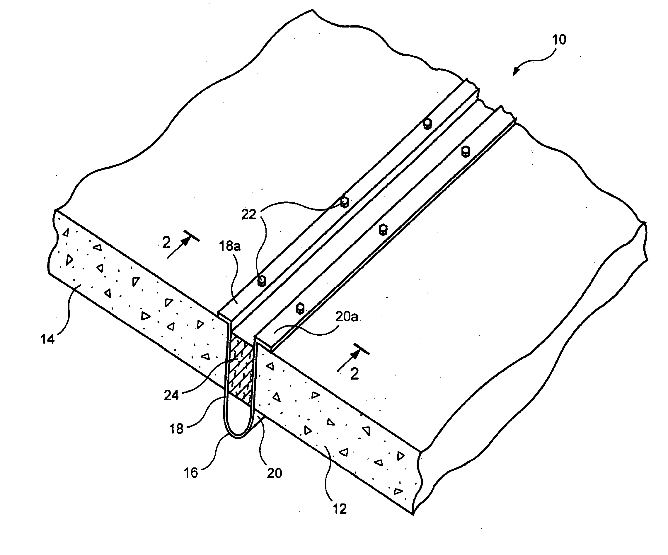
[0007] In accordance with the invention, this object is achieved with a two-piece joint system comprising a strip of fire-resistant, flexible sheet material formed into a U-shaped trough or drape and an elongated mat of expandable fire-resistant mat retained within the drape. The edges of the flexible drape are bent outwardly to overlay the surfaces of the adjacent building panels and secured thereto by suitable fasteners. Little or no adhesives and no sealants are required to secure the joint in place and the impervious nature of the drape guards against the chimney effect. The savings in installation time and cost of the invention provides a further significant advantage over prior art systems.

Problems solved by technology

Over time, the joint material tends to dry out and pull away from the opposed concrete surfaces.
While this effect poses little problem in concrete slabs poured on grade, it is a matter of significant concern when the slabs constitute the floors of a multilevel structure.
Not only would the joint material tend to separate from the slabs over time, it could even fall out completely during periods of extreme contraction.
While the material described in the above-mentioned patent, manufactured and sold by Backer Rod Manufacturing, Inc. of Denver, Colo., under the name Ultra Block, has suitable heat-resistance and expansion characteristics for building applications, the manner disclosed in the patent for securing the material between building panels is relatively complex and suffers the disadvantage that the sealing rods and elastomer used to retain the material in place are subject to drying over time and dropping out.

Method used


Image

  • Fire barrier system for building panels
  • Fire barrier system for building panels
  • Fire barrier system for building panels

Examples


Embodiment Construction

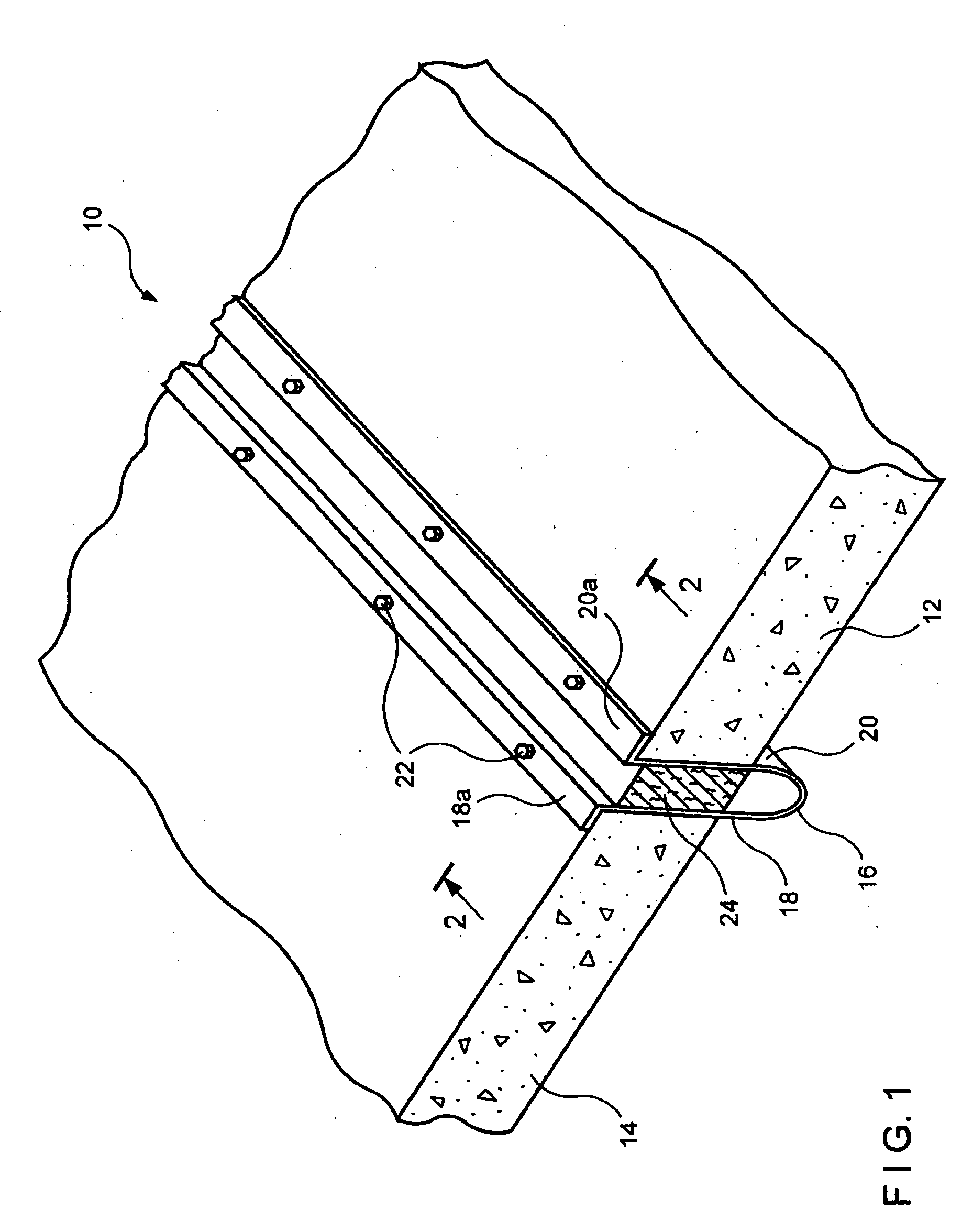
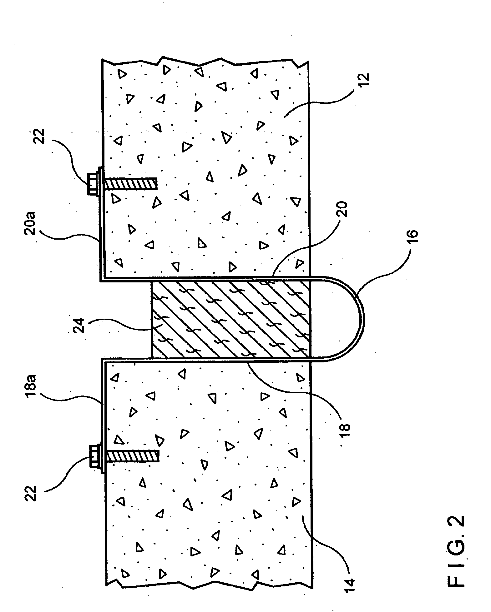
[0013] Referring now to the drawings, FIGS. 1 and 2 illustrate the novel expansion joint of the invention as installed between adjacent building panels of a structure. In this example, the building panels are shown as adjacent horizontal concrete slabs 12, 14 forming part of a floor of a structure, but it will be understood that the invention is applicable to adjacent vertical wall panels as well.

[0014] The joint structure 10 comprises a heat shield or drape 16 made of 2 mil (0.002 inch) thick impermeable stainless steel foil, formed into a longitudinally extending generally U-shaped trough, the opposite legs of which are indicated at 18 and 20. The legs 18, 20 are bent along their longitudinal edges at 90° to form flanges 18a and 20a. The drape 16 can be either metallic or woven ceramic. The drape 16 can also be woven from fire retardant fabric and should be flexible. When installed between slabs 12 and 14, the flanges overlay the upper surfaces of the adjacent slabs and bolts or ...


PUM


Abstract

An expansion joint for building panels, such as concrete floor slabs, comprises a U-shaped drape of a flexible, fire-resistant, impermeable material such as stainless steel foil. The opposite legs of the U-shaped drape are fastened between respective adjacent slabs and a mat of expandable fire-resistant material inserted within the U-shaped drape between the slabs. The impermeability and flexibility of the drape, coupled with the insulating property of the mat provide an inexpensive, effective fire seal between building panels that can also accommodate seismic displacement.

Description

FIELD OF THE INVENTION [0001] The present invention relates generally to expansion joints for building panels and more particularly to expansion joints for building panels such as concrete floor slabs that provide the necessary flexibility for expansion and contraction and at the same time, block fire and heat flow between adjacent panels. BACKGROUND OF THE INVENTION [0002] It is generally understood that in building construction, it is necessary to provide expansion joints between abutting floor or wall panels to allow for expansion and contraction of the material under varying temperatures. In concrete construction, such joints typically comprise a strip of a relatively soft material interposed between the edges of abutting slabs of concrete when poured. Over time, the joint material tends to dry out and pull away from the opposed concrete surfaces. While this effect poses little problem in concrete slabs poured on grade, it is a matter of significant concern when the slabs consti...

Claims


Application Information

Patent Timeline
Patent Type & Authority Applications(United States)
IPC IPC(8): E04B1/68E04B1/94E04B5/02
CPCE04B1/6804E04B5/023E04B1/948
Inventor BARR, ROGER
Owner E M E H
Learn More