Corrosion resistant prestressed concrete float system

a prestressed concrete and float system technology, applied in the direction of groynes, special-purpose vessels, vessel construction, etc., can solve the problems of corroding wire reinforcement mesh and weakening the strength of the dock

Inactive Publication Date: 2005-05-19
THOMSON HOWARD M
View PDF15 Cites 27 Cited by
  • Summary
  • Abstract
  • Description
  • Claims
  • Application Information

AI Technical Summary

Problems solved by technology

It has been observed that over time, particularly when the dock or other float structures are used in a saltwater environment, that the cables and wire reinforcing mesh may corrode and weaken the strength of the dock.

Method used


Image

  • Corrosion resistant prestressed concrete float system
  • Corrosion resistant prestressed concrete float system
  • Corrosion resistant prestressed concrete float system

Examples


Embodiment Construction

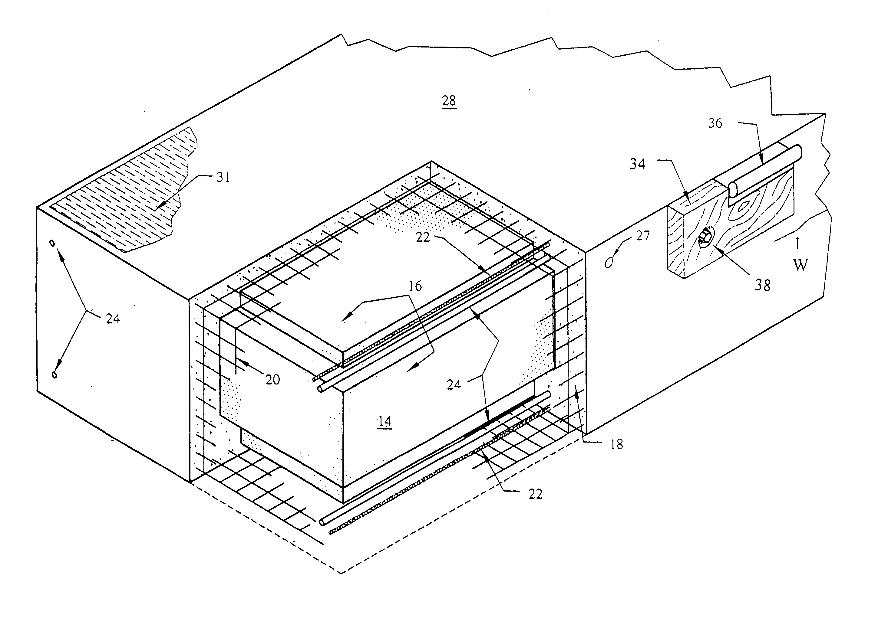
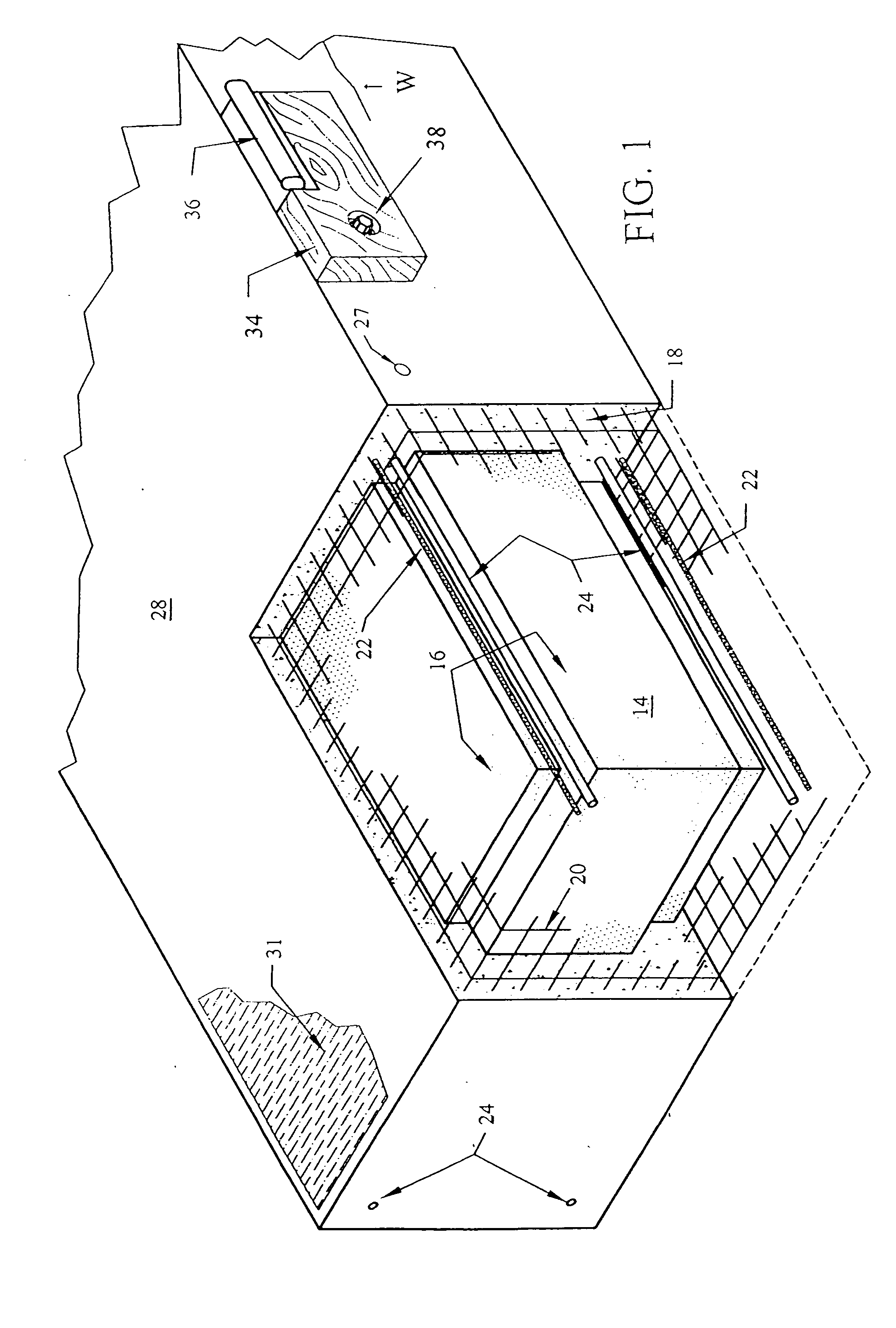
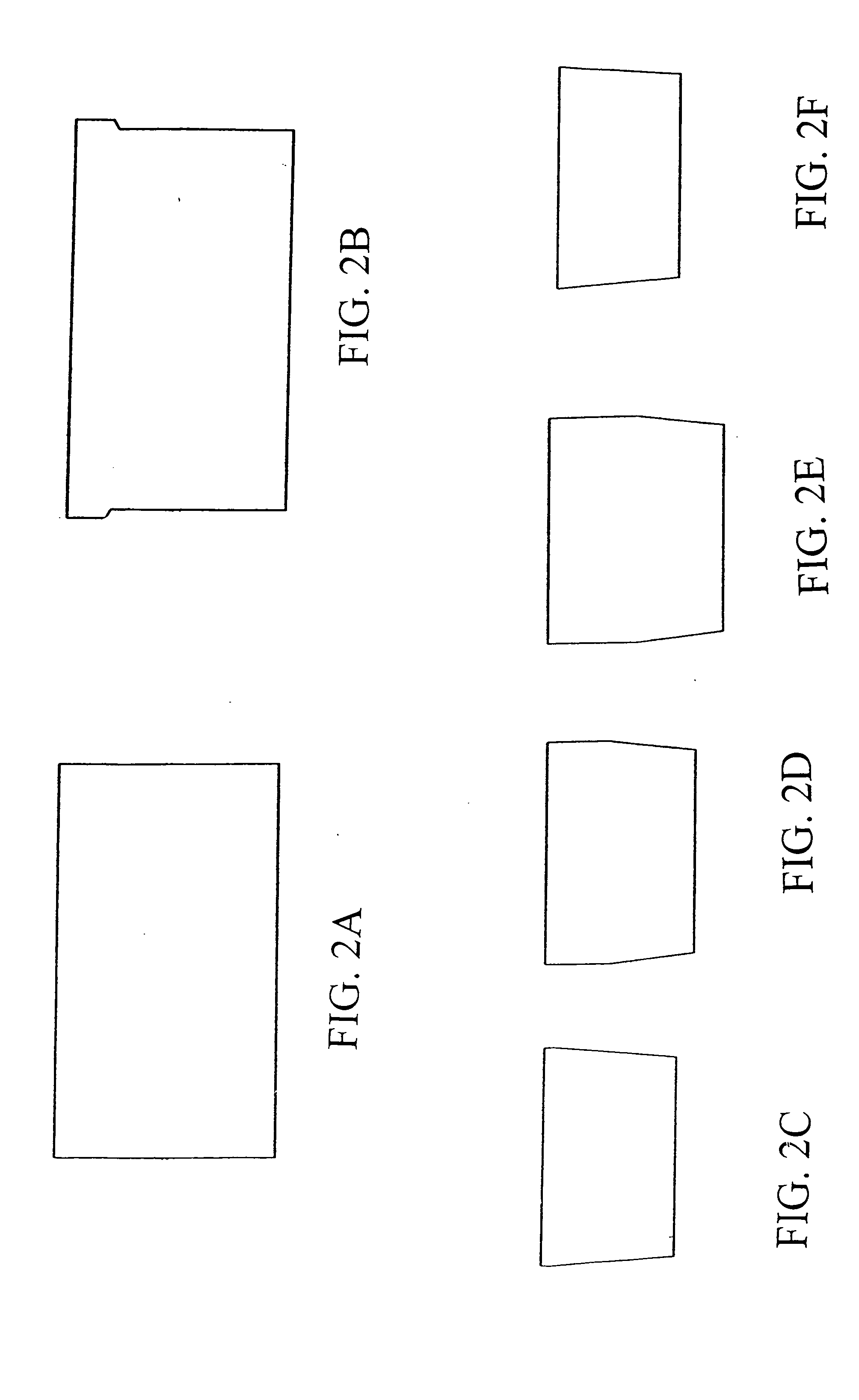
[0012] With reference to the drawings, the invention relates to a corrosion resistant prestress concrete float system featuring one or more floating units 10. Each unit 10 preferably has a cross-section configuration as depicted in FIGS. 2A-2F, but may also be configured to have other cross-sections. A plurality of the units 10 may be arranged as seen in FIG. 3 and FIGS. 5A-5B to provide a floating dock or wharf system 12.

[0013] Returning to FIG. 1, each unit 10 is constructed so as to be relatively corrosion resistant when used in a marine environment. This is accomplished in a preferred embodiment by avoiding the use of components such as steel in the construction of the units 10.

[0014] In a preferred embodiment, each unit 10 preferably includes a buoyant core 14 encased within a polymeric coating 16, concrete 18 encasing the core 14 and polymeric coating 16, a corrosion resistant mesh 20 to reinforce the concrete 18, and a plurality of corrosion resistant pretensioned fiber mem...


PUM

PropertyMeasurementUnit
lengthaaaaaaaaaa
corrosionaaaaaaaaaa
corrosion resistantaaaaaaaaaa

Abstract

A corrosion resistant prestressed float unit including a buoyant core encased within a polymeric coating, concrete encasing the core and polymeric coating, a corrosion resistant mesh to reinforce the concrete, and a plurality of corrosion resistant pretensioned fiber members extending the entire length of the unit.

Description

FIELD OF THE INVENTION [0001] This invention relates generally to prestressed concrete flotation structures. More particularly, this invention relates to floating prestressed concrete structures which are more corrosion resistant than conventional floating concrete structures. BACKGROUND AND SUMMARY OF THE INVENTION [0002] Prestressed concrete floatation structures are well known for use as docks, wharves, and the like. Such structures, such as described in U.S. Pat. No. 3,799,093 entitled FLOATING PRESTRESSED CONCRETE WHARF, include a buoyant material, such as expanded polystyrene, a layer of concrete surrounding the buoyant material, reinforcing wire mesh surrounding the buoyant material and located within the concrete layer, and pretensioned steel cables extending through the concrete to maintain it in compression. It has been observed that over time, particularly when the dock or other float structures are used in a saltwater environment, that the cables and wire reinforcing mes...

Claims


Application Information

Patent Timeline
Patent Type & Authority Applications(United States)
IPC IPC(8): B63B5/14B63B35/38E02B3/06
CPCB63B5/14B63B35/38E02B3/064B63B2231/68B63B2231/62
Inventor THOMSON, HOWARD M.
Owner THOMSON HOWARD M
Why Eureka
Try Eureka