Automatic inspection and imaging electrophoresis device

an electrophoresis and automatic inspection technology, applied in the direction of electrolysis components, instruments, separation processes, etc., can solve the problems of inability to always be controlled precisely, poor resolution, liquid tends to expand

an electrophoresis and automatic inspection technology, applied in the direction of electrolysis components, instruments, separation processes, etc., can solve the problems of inability to always be controlled precisely, poor resolution, liquid tends to expand

US20050103633A1Inactive Publication Date: 2005-05-19PACIFIC IMAGE ELECTRONICS

Image

  • Automatic inspection and imaging electrophoresis device
  • Automatic inspection and imaging electrophoresis device
  • Automatic inspection and imaging electrophoresis device

Examples


Embodiment Construction

[0023] Reference will now be made in detail to the preferred embodiments of the present invention, examples of which are illustrated in the accompanying drawings. Wherever possible, the same reference numbers are used in the drawings and the description to refer to the same or like parts.

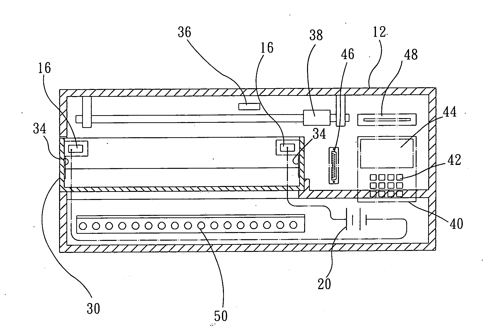
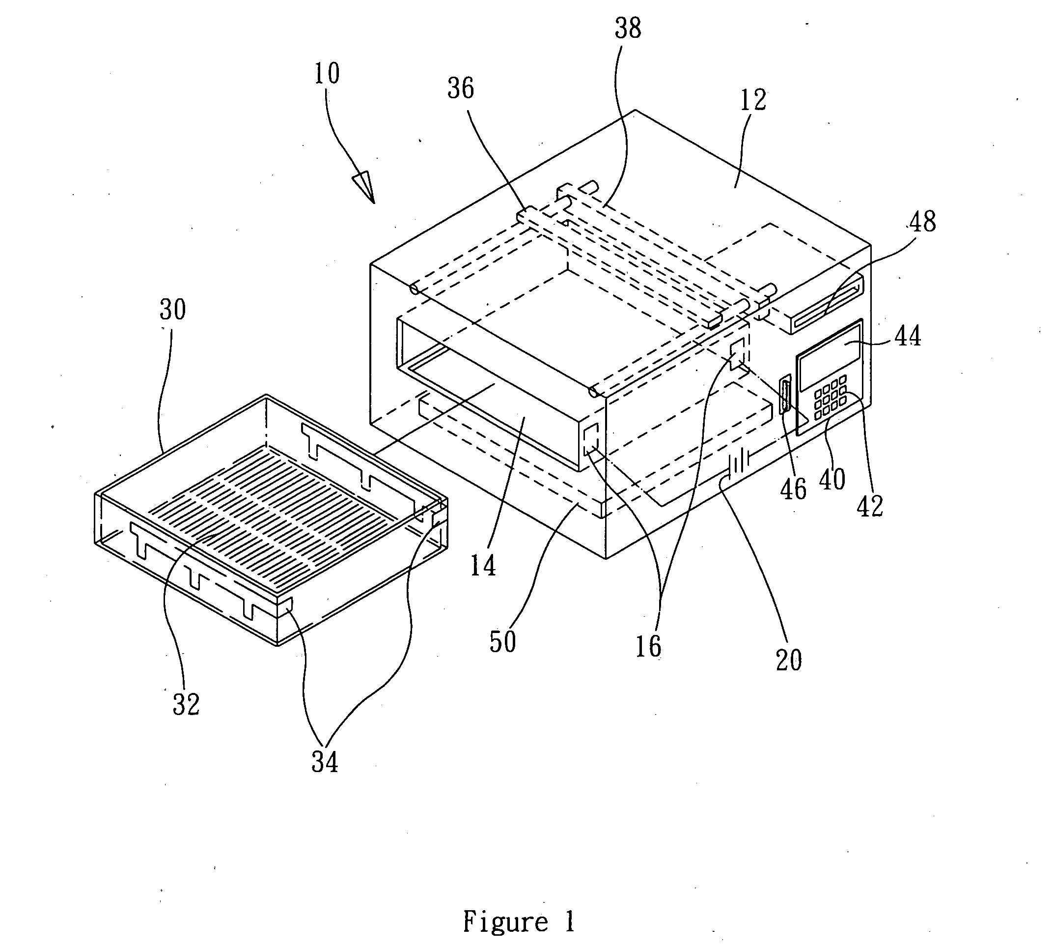
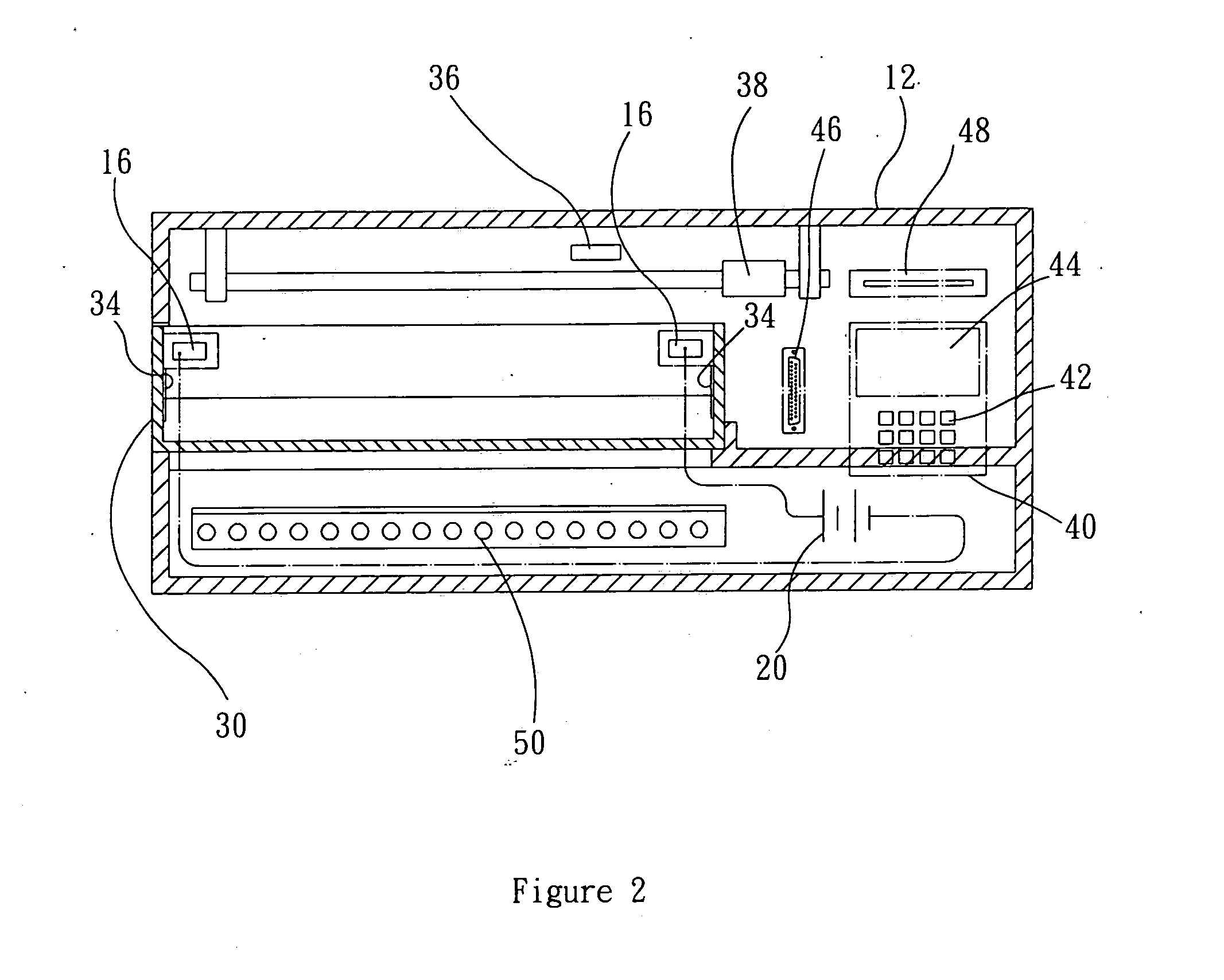
[0024] The automatic inspection and imaging electrophoresis analysis device of the present invention improves the traditional technology of electrophoresis analysis. With the conventional method, after completing electrophoresis, the sample is moved to an analysis tank to complete imaging. The process is complex and the duration of mobility is difficult to control, resulting in imaging with poor resolution. The present invention provides an automatic monitoring and imaging device with combined electrophoresis analysis and automatic control, in order to automatically monitor the processes of electrophoresis analysis and imaging so as to achieve accurate electrophoresis results.

[0025] Refer to FIGS....


PUM

PropertyMeasurementUnit
transparentaaaaaaaaaa
sizeaaaaaaaaaa
frictionaaaaaaaaaa

Abstract

An automatic monitoring and imaging electrophoresis device. The device comprises a combined electrophoresis tank and electrophoresis analyzing equipment. The device further comprises features such as time setting, instant sensor, instant imaging, and automatic storage. It also contains components that provide a power source, sensor, light source, scanner, and storage; and an electrophoresis tray for samples in order to complete the operations of electrophoresis mobility and analysis with the same device. The electrophoresis analysis device overcomes the disadvantages of restricted operating mobility and separate analysis, as well as providing simplicity, safety and efficiency to users.

Description

BACKGROUND OF THE INVENTION [0001] 1. Field of the Invention [0002] The present invention relates to an electrophoresis analysis device. More specifically, the present invention discloses an automatic inspection and imaging electrophoresis analysis device. [0003] 2. Description of the Prior Art [0004] Electrophoresis is a very important technology in the molecule inspection field. Electrophoresis is a method of separating large molecules from a mixture of similar molecules. An electric current is passed through a medium containing the mixture, and each kind of molecule travels through the medium at a different rate, depending on its electrical charge and size. Separation is based on these differences. [0005] Mobility is directly proportional to the electric density of a molecule; and is inversely proportional to the friction of the molecule. The friction is related to the size and shape of the molecule. If the mass of the molecule is large, then the friction is large. If the mobilit...

Claims


Application Information

Patent Timeline
19 May 2005
Publication
US20050103633A1
IPC
G01N27/447
CPC
G01N27/44756; G01N27/44721
Inventors
TSENG, CHIH-YUAN