
Injection moulding of a catheter

a catheter and injection moulding technology, applied in the field of catheters, can solve the problems of complex moulding of one-piece soft needle catheters, risk of separation, and inability to form kinks, and achieve the effect of reducing production costs and simplifying the production process

Active Publication Date: 2005-05-19
UNOMEDICAL AS
View PDF14 Cites 27 Cited by
  • Summary
  • Abstract
  • Description
  • Claims
  • Application Information

AI Technical Summary

Benefits of technology

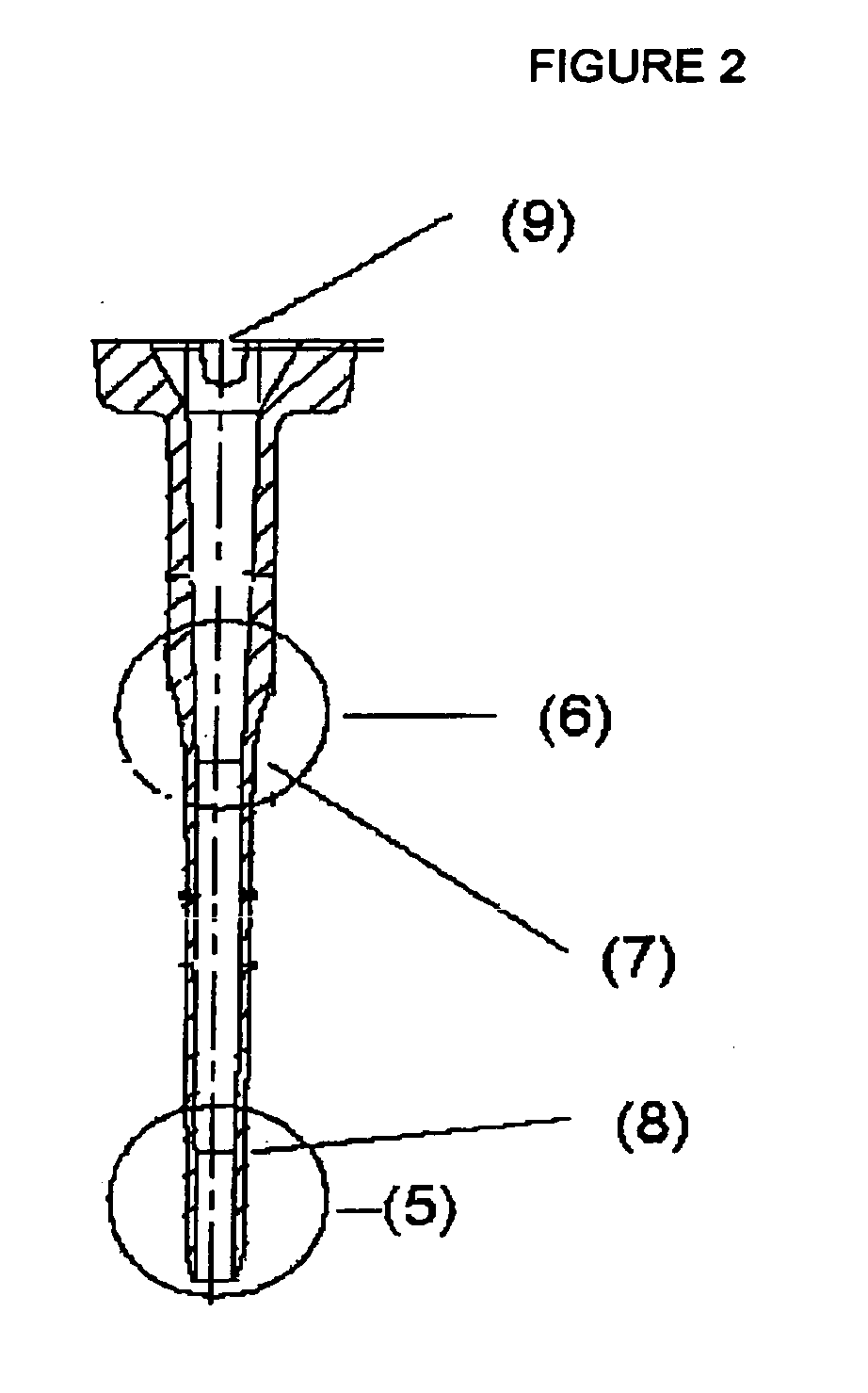
[0013] It has been discovered that by extending the cone-shaped part of the core for creating the interior of the soft needle catheter, from the hub and further into the tube-shaped part, it is possible to remove the core after moulding without wrinkling of the tube-shaped part. Therefore it is now possible to mould soft needle catheters without the assistance of gas and / or sleeves. This makes the production process cheaper and simpler.

Problems solved by technology

However it must not be so flexible that it is capable of forming kinks which may stop the drug delivery.
A two piece catheter is easier to manufacture but it suffers from the drawback that there is a risk of separation, especially during removal of the catheter, leaving the tube-shaped part in the body cavity.
Moulding of one-piece soft needle catheters is complicated due to the dimensions of the catheter.
There is a risk that the tube-shaped part wrinkles during removal from the mould form either as a consequence of the withdrawal of the core creating the hollow part or as a consequence of sticking to the mould.
During moulding there is a risk that a fin forms at the splitting line of the mould.
A fin placed at the middle of the tube-shaped part might cause unnecessary pain or even cuts to a patient during penetrations of the skin.
Use of sleeves complicates the production and increases the production costs.

Method used


Image

  • Injection moulding of a catheter
  • Injection moulding of a catheter
  • Injection moulding of a catheter

Examples


example 1

[0059] Three selected materials, LDPE Lupolen 3020D, LDPE Lupolen 1840H and Hostaform MT24U01 were tested according to the described methods. The results are listed below:

LDPELDPELupolenLupolenHostaformTest3020D1840HMT24U01IntroductionApprovedApprovedApprovedforcePeelbackApprovedApprovedApprovedKink-angleApprovedNot-approved—TensileApprovedApprovedApprovedstrengthGeneralUsableUsableVery hardopinionmaterial -material -materialacceptablyacceptablybendable andbendable andsoft -soft -but lacks thebut lacks theelasticelasticelementelement

example 2

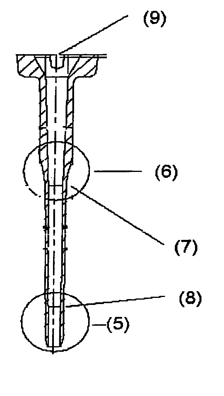
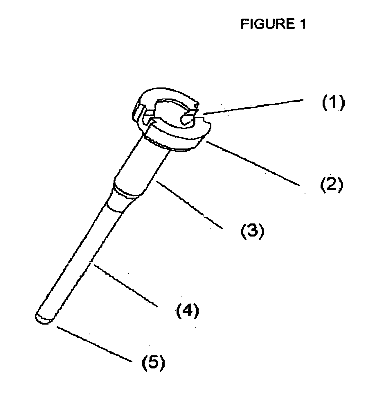
[0060] In FIG. 1 a preferred soft needle catheter according to the invention is shown. The catheter comprises a hub (3) and a tube-shaped part (4). The hub further comprises a rim (2) having a carving (1). The tube-shaped part is rounded at the cylindrical part (5) of the tube-shaped part. FIG. 2 shows the preferred soft needle catheter according to the invention in a cross sectional view. It can be seen that the hub decreases its-diameter in a zone (6) until it has the same diameter as the tube-shaped part which begins at (7). The tube-shaped part has a cone-shaped part extending from (7) to (8) and a cylindrical part (5). Further it can be seen that the core. (9) has a cone-shaped part extending into the tube-shaped part (from the top to (8)) and a cylindrical part (from, (8) and the rest of the core)). FIG. 3 shows an enlargement of the cylindrical part of tube-shaped part. In this embodiment is seen how the cylindrical part is rounded (10) and has the dimension 1.5 mm long and w...


PUM

PropertyMeasurementUnit
Lengthaaaaaaaaaa
Electric dipole momentaaaaaaaaaa

Abstract

A method for one-piece injection molding of a soft needle catheter having a hub and a tube-shaped flexible part. According to the method, a molten polymer is fed into a mold which includes a core that is used to form the interior of the catheter, the core defining a hub cavity and a tube-shaped cavity. The hub cavity includes a cone-shaped part and a cylindrical part, with the cone-shaped part extending into the tube-shaped cavity. When the polymer is sufficiently cured, the core is removed from the catheter and the catheter is removed from the mold.

Description

FIELD OF INVENTION [0001] The present invention relates to catheters and an improved method of producing such catheters. BACKGROUND [0002] In general a catheter is a device for transporting a fluid to or from a body cavity. Often catheters comprise a tube-shaped part which facilitates the fluid transport. [0003] A subgroup of catheters is known as soft needle catheters and they have a wide range of applications, e.g. in automated drug delivery devices such as insulin delivery devices. The soft needle catheters are in general more flexible and softer than other catheters. [0004] The soft needle catheters are generally used together with an Introducer needle, where the needle is used to penetrate the barrier to the body e.g. the skin and assist the introduction of the catheter. The needle is removed after introduction of the catheter into a body cavity. The soft needle catheter is left in the body cavity for a desired period of time in which it functions as the means for drug delivery...

Claims


Application Information

Patent Timeline
IPC IPC(8): A61M25/00B29C45/16B29C45/26B29C45/36B29C45/40
CPCA61M25/0009B29C45/16B29C45/261B29L2031/7542B29C45/40B29K2221/003B29C45/36
Inventor MEJLHEDE, SIGNE THORNINGGYRN, STEFFEN
Owner UNOMEDICAL AS
Learn More