Telescopic shaft for steering vehicle and telescopic shaft for steering vehicle with cardan shaft coupling

a technology of telescopic shafts and steering shafts, which is applied in the direction of bearing unit rigid support, pedestrian/occupant safety arrangement, tractors, etc., can solve the problems of increasing the abraded film of nylon with the elapse of use, the inability to achieve the effective utilization of space, and the inability to reduce both the number of parts and manufacturing costs. , to achieve the effect of reducing manufacturing costs, high rigidity and high rigidity

Active Publication Date: 2005-05-19
NSK LTD
View PDF14 Cites 37 Cited by
  • Summary
  • Abstract
  • Description
  • Claims
  • Application Information

AI Technical Summary

Benefits of technology

[0050] In the telescopic shaft for the steering of the vehicle according to the fourth invention, preferably, the elastic body is constructed of a leaf spring. Thus, the elastic body is constructed of the leaf spring, whereby the steering characteristic giving the feeling of the desired high rigidity can be obtained while restraining the manufacturing costs.
[0051] In the telescopic shaft for the steering of the vehicle according to the fourth invention, preferably, the biasing portion provided as the separate portion and formed of the different material and the second biasing portion provided as the separate portion and formed of the different material, are made of a rubber or a synthetic resin. Thus, the biasing portion provided as the separate portion and formed of the different material and the second biasing portion provided as the separate portion and formed of the different material, are made of the rubber or the synthetic resin, whereby the stress generated at the biasing portion when the torque is transferred can be made comparatively small, and the steering characteristic giving the feeling of desired high rigidity can be acquired.
[0052] In the telescopic shaft for the steering of the vehicle according to the fourth invention, preferably, a lubricating agent is applied between the axially-extending groove of the male shaft, the axially-extending groove of the female shaft, the elastic body and the first torque transfer member. Thus, the lubricating agent is applied between the axially-extending groove of the male shaft, the axially-extending groove of the female shaft, the elastic body and the first torque transfer member, whereby when the torque is not transferred (when sliding), the male shaft and the female shaft can slide in the axial direction with the stable slide load without any backlash.
[0053] From what has been discussed so far, according to the fourth invention, the stress generated on the elastic body is relieved, whereby the pre-load performance required over the long period of time can be maintained by preventing the “fatigue” of the elastic body. Further, there is no necessity of setting the dimensional accuracy strict, and the reduction in the costs can be actualized. Moreover, the steering performance required can be easily obtained because of being structured so that the friction between the elastic body and the axially-extending groove can be controlled.

Problems solved by technology

This is a comparatively narrow portion, and nevertheless a scheme of effectively utilizing the space can not be attained.
Further, this is a hindrance to decrease both the number of parts and manufacturing costs.
It might, however, happen that the film of nylon is increasingly abraded with an elapse of its use, with the result that the backlash in the rotating direction augments.
Further, under a condition of being exposed to a high temperature within an engine room, the film of nylon changes in its volume and remarkably increases in slide resistance, and the abrasion thereof is conspicuously accelerated, resulting in an increase in the backlash in the rotating direction.
Note that a scatter in working accuracy, if any, is not allowable with the quantity of flexure to that extent.
Secondly, when the torque is inputted, the male shaft, the leaf spring, the spherical members and the female shaft get narrow down each other and thus transfer the torque, and therefore an extremely high surface pressure occurs at a contact point between the spherical member and the leaf spring.
Namely, when the torque is transferred, a high stress occurs on the leaf spring, with the result that a “fatigue” of the leaf spring is induced by a permanent deformation, pre-load performance becomes hard to maintain over a long period of time, and this might be a hindrance to gain a longer life-time of the steering shaft.
Thirdly, when the torque is transferred, the leaf spring slides sideways in the peripheral direction from the axially-extending groove, whereby a decline of the transfer torque is induced, a degree of hysteresis can not be managed, and the hysteresis might excessively occur.
Fourthly, when a torque load is not applied, the contact points between the male shaft, the spherical member, the leaf spring and the female shaft do not exist on the same line, and hence contact angles change as the torque load is applied.

Method used


Image

  • Telescopic shaft for steering vehicle and telescopic shaft for steering vehicle with cardan shaft coupling
  • Telescopic shaft for steering vehicle and telescopic shaft for steering vehicle with cardan shaft coupling
  • Telescopic shaft for steering vehicle and telescopic shaft for steering vehicle with cardan shaft coupling

Examples


first embodiment

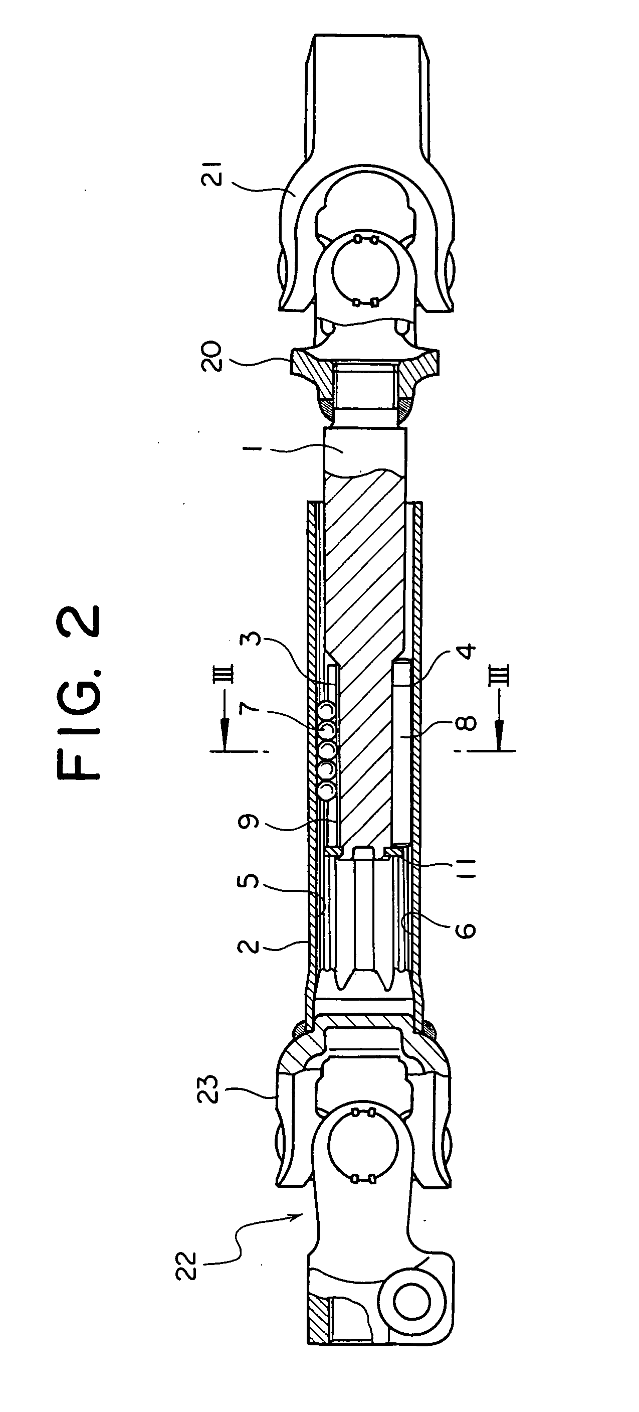
[0098]FIG. 2 is a vertical sectional view of the telescopic shaft for the steering of the vehicle with a Cardan shaft joint according to a first embodiment of the present invention. FIG. 3 is an exploded perspective view of the telescopic shaft for the steering of the vehicle shown in FIG. 2. FIG. 4 is a cross-sectional view taken along the line III-III in FIG. 2. FIG. 5 is a graph (a part 1) showing a relationship between a steering torque and a rotational angle. FIG. 6 is a graph (a part 2) showing the relationship between the steering torque and the rotational angle. FIG. 7 is a graph (a part 3) showing the relationship between the steering torque and the rotational angle.

[0099] As illustrated in FIG. 2, the telescopic shaft for the steering of the vehicle (which will hereinafter be termed an “telescopic shaft”) is constructed of a male shaft 1 and a female shaft 2 that are fitted so as not to be rotatable but to be slidable on each other.

[0100] The male shaft 1 is connected to...

second embodiment

[0126]FIG. 12A is a vertical sectional view of the telescopic shaft for the steering of the vehicle with a Cardan shaft joint according to a second embodiment of the present invention. FIG. 12B is a cross-sectional view taken along the line b-b in FIG. 12A.

[0127]FIG. 13A is a side view including a partial cut-off section of a sub-assembly of the telescopic shaft for the steering of the vehicle with the Cardan shaft joint shown in FIGS. 12A and 12B. FIG. 13B is a side view including a partial cut-off section of a female shaft. FIG. 13C is a front view of the female shaft as viewed from the left side.

[0128]FIG. 14 is a graph showing a relationship between the steering torque and the rotational angle in the second embodiment.

[0129] In the second embodiment, a buffer member 30 structured by charging a space between an inner ring 31 and an outer ring 32 with a rubber 33, is provided between an end portion of a female shaft 2 and a yoke 23 of a Cardan shaft joint 22. When the steering ...

third embodiment

[0140]FIG. 16A is a vertical sectional view of the telescopic shaft for the steering of the vehicle with the Cardan shaft joint according to a third embodiment of the present invention. FIG. 16B is a cross-sectional view taken along the line b-b in FIG. 16A.

[0141]FIG. 17 is a side view including a partial cut-off section of the female shaft of the telescopic shaft for the steering of the vehicle with the Cardan shaft joint shown in FIGS. 16A and 16B.

[0142] In the third embodiment also, the buffer member 30 structured by charging the space between the inner ring 31 and the outer ring 32 with the rubber 33, is provided between the end portion of the female shaft 2 and the yoke 23 of the Cardan shaft joint 22. When the steering torque is equal to or smaller than the predetermined level, the buffer member 30 can buffer and thus reduce the uncomfortable noises and vibrations transferred from the engine room.

[0143] Moreover, as shown in FIGS. 16A and 17, the yoke 23 is formed with an e...


PUM


Abstract

A telescopic shaft for steering of a vehicle is assembled in a steering shaft and includes a male shaft and a female shaft that are so fitted as not to be rotatable but to be slidable. Rolling members are fitted through an elastic body for pre-load between at least a pair of axially-extending grooves formed in an outer peripheral surface of the male shaft and in an inner peripheral surface of the female shaft. A slide member is fitted in between at least another pair of axially-extending grooves formed in the outer peripheral surface of the male shaft and in the inner peripheral surface of the female shaft. When a steering toque is equal to or smaller than a predetermined level, the elastic body for the pre-load exhibits a low rigidity characteristic as the elastic body performs pre-load action. When the steering torque is equal to or larger than the predetermined level, the slide member exhibits a high rigidity characteristic as the slide member engages with the pair of axially extending grooves.

Description

TECHNICAL FIELD [0001] The present invention relates to a telescopic shaft for steering of a vehicle and a telescopic shaft for steering of a vehicle with a Cardan shaft joint. BACKGROUND ARTS [0002] In a steering apparatus for a vehicle, an intermediate shaft is provided, for instance, between a Cardan shaft joint provided on the side of a steering shaft and a Cardan shaft joint provided on the side of a steering gear. [0003] The intermediate shaft is constructed of a male shaft and a female shaft that are so spline-fitted, etc. as not to be rotatable but to be slidable on each other. The intermediate shaft is structured to be capable of transferring a steering torque in a high rigidity state while preventing a backlash in order to surely transfer the steering torque given from a driver to the steering gear, absorbing an axis-directional displacement caused when the vehicle travels, and sliding (expandable / retractable) in the axial direction with a comparatively low and stable slid...

Claims


Application Information

Patent Timeline
Patent Type & Authority Applications(United States)
IPC IPC(8): B62D1/16B62D1/185B62D1/20F16C3/035F16C25/08F16C27/06F16C29/00F16C29/04F16C29/12F16C33/58F16C33/62F16D3/06
CPCB62D1/16B62D1/185B62D1/20F16C3/035F16C29/002F16C29/04Y10T403/7026F16C33/58F16C33/62F16D3/06F16D3/065F16C2326/24F16C29/123F16C29/007
Inventor YAMADA, YASUHISASHODA, AKIHIROOZAWA, ATSUSHIYUKAWA, KINJIYAMADA, TAKATSUGU
Owner NSK LTD
Why Eureka
Try Eureka