Bumper system

a bumper system and bumper technology, applied in the field of bumper systems, can solve the problems of bumper systems no longer able to meet safety test requirements for approval, and the increase in the capacity of energy absorption cannot normally be achieved, so as to reduce the amount of installation space, reduce the effect of energy consumption and reducing the capacity of energy absorption on impa

Inactive Publication Date: 2005-05-19
ALCAN TECH & MANAGEMENT LTD
View PDF9 Cites 41 Cited by
  • Summary
  • Abstract
  • Description
  • Claims
  • Application Information

AI Technical Summary

Benefits of technology

[0007] The object of the present invention is to develop bumper systems further such that these are capable of absorbing a greater amount of energy on impact without an undue increase in the dimensions or weight of the vehicle fitted with the bumper system. In addition, a further developed bumper system should also be suitable for vehicles with a reduced amount of space for installation of the bumper system, this without significantly reducing the capacity for energy absorption on impact compared to conventional bumper systems. Further, the manufacture and handling of the bumper system should be very simple.

Problems solved by technology

If for example the space available for the bumper system in a vehicle is smaller than in previous vehicles, then the bumper system and in particular along with that also the cross beams and the deformation elements have to be re-dimensioned—which as a rule leads to a reduction in the capacity for energy absorption on impact—with the result that in some cases the bumper systems are no longer able to meet the safety test requirements for approval.
In that case the increase in capacity for energy absorption can not normally be achieved by increasing the dimensions of previously employed bumper systems.

Method used


Image

  • Bumper system
  • Bumper system
  • Bumper system

Examples


Embodiment Construction

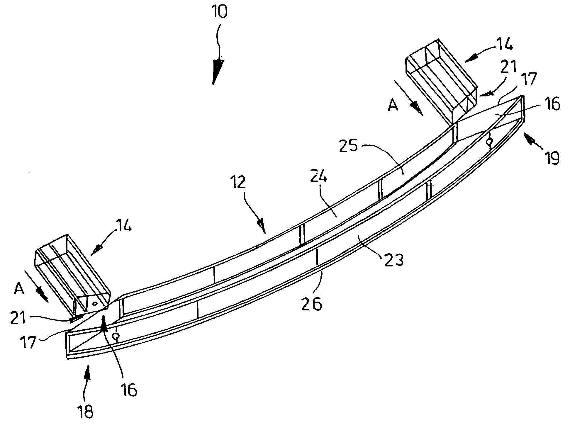
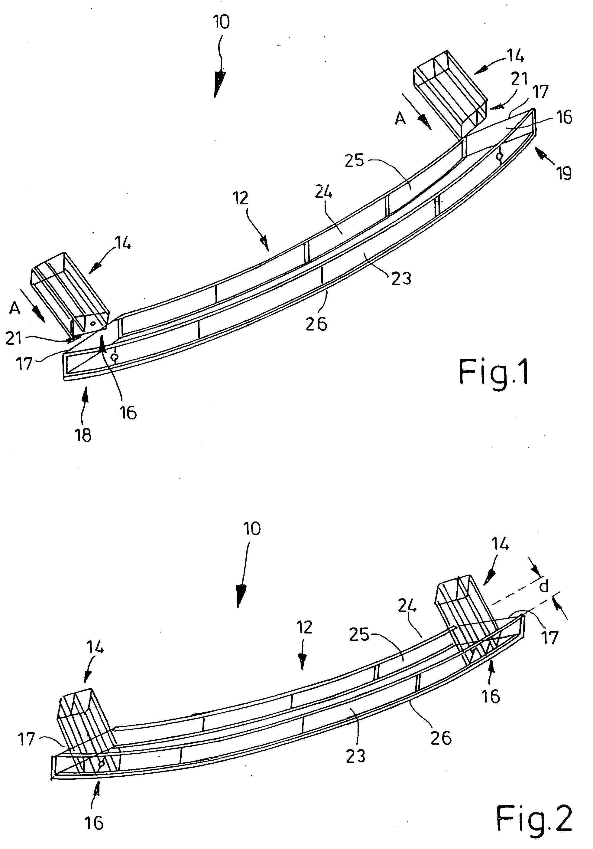
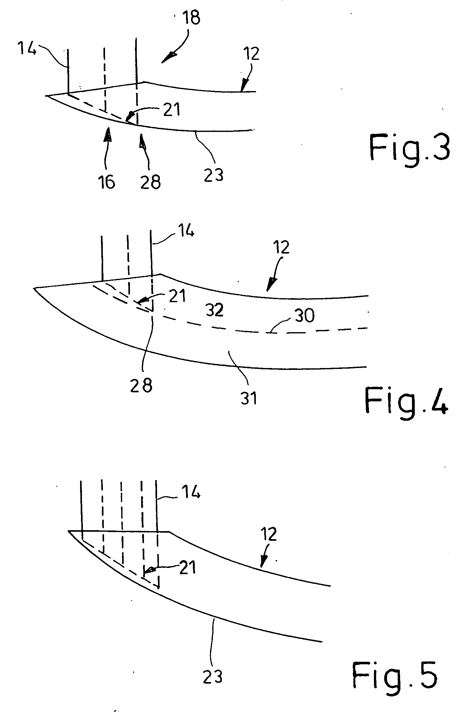
[0037] Shown in FIG. 1 is a bumper system 10 yet to be assembled. The bumper system 10 is comprised of a cross beam 12 and two crash-boxes 14 (deformation elements) which, for assembly of the finished bumper system 10, are pushed in the direction of the arrow A into appropriately shaped recesses 16 in the cross beam 12. The recesses 16 are formed in the outer ends 18 and 19 of the cross beam 12.

[0038] The vehicle, not shown here for reasons of clarity, is situated on the side of the crash-boxes 14 opposite that of the arrow A.

[0039] In the example shown, the cross beam 12 and the crash-boxes 14 are made of an extruded aluminum alloy. The cross beam 12 is in the form of a single chamber hollow section whereas the crash-boxes 14 are in the form of two-chamber hollow sections. The openings 17 through which the crash-boxes 14 are introduced into the recesses 16 are e.g. formed by an inclined saw cut or by a milling operation. The slight curvature in the cross beam 12 can be achieved b...


PUM


Abstract

A bumper having crash-boxes accommodated at least in part by space in a hollow cross beam section. As a result, when impact due to collision occurs, deformation of the crash-box takes place early, so that for the same outer dimensions of the bumper longer crash-boxes can be employed. This is of advantage as the energy absorbed by the compression of the cross beam is small in relation to the mass employed and the distance traversed compared with the that achieved with crash-boxes. The capacity to absorb energy exhibited by the proposed bumper is therefore greater than that achieved by conventional bumpers.

Description

BACKGROUND OF THE INVENTION [0001] The invention relates to a bumper system for attachment to a vehicle having a cross beam element and at least one deformation element, situated between the cross beam element and the vehicle, which serves to dissipate energy on collision of the vehicle. [0002] Known bumper systems normally contain a cross beam which can be joined to, or feature, attachment means. The attachment means serve the purpose of attaching the bumper system e.g. to a vehicle. Should the vehicle collide with a solid object, the cross beam is deformed, thereby absorbing the energy of impact. The cross beams are often hollow sections, with the result that the absorption of the energy of impact is effected by compression of the hollow section perpendicular to its longitudinal direction. The cross beam is designed such that the force at which it begins to deform is lower than the force necessary to deform the vehicle structure. In the case of a minor collision, therefore, initia...

Claims


Application Information

Patent Timeline
Patent Type & Authority Applications(United States)
IPC IPC(8): B60R19/18B60R19/34
CPCB60R19/18B60R2019/182B60R2019/1806B60R19/34
Inventor LIEBHARD, OLIVERGEHRIG, MARKUSLEPPIN, CHRISTIAN
Owner ALCAN TECH & MANAGEMENT LTD
Why Eureka
Try Eureka