Mid-roller wheels for endless drive track system

a technology of endless drive track and mid-roller, which is applied in the direction of mechanical control devices, instruments, hoisting equipment, etc., can solve the problems of guide lugs fracturing, the source of wear of components, and the friction between guide lugs and mid-rollers is probably the worst source of wear

Inactive Publication Date: 2005-05-19
CAMOPLASY INC
View PDF5 Cites 23 Cited by
  • Summary
  • Abstract
  • Description
  • Claims
  • Application Information

AI Technical Summary

Problems solved by technology

The contact between the guide lugs passing through the drive wheel, idler and each of the mid-rollers is a source of wear for the components.
Friction between guide lugs and mid-rollers are probably the worst source of we

Method used


Image

  • Mid-roller wheels for endless drive track system
  • Mid-roller wheels for endless drive track system
  • Mid-roller wheels for endless drive track system

Examples


Embodiment Construction

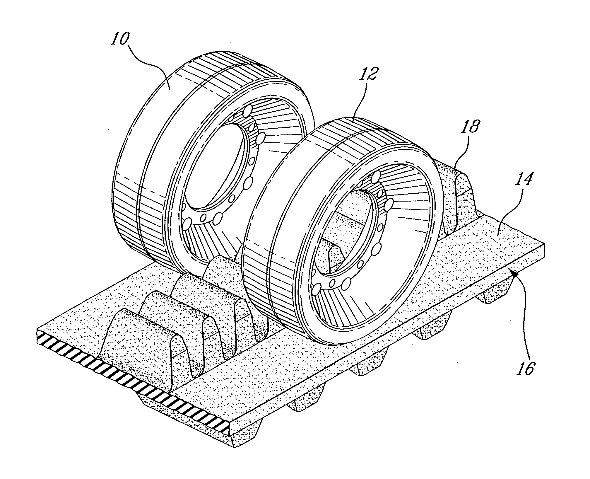
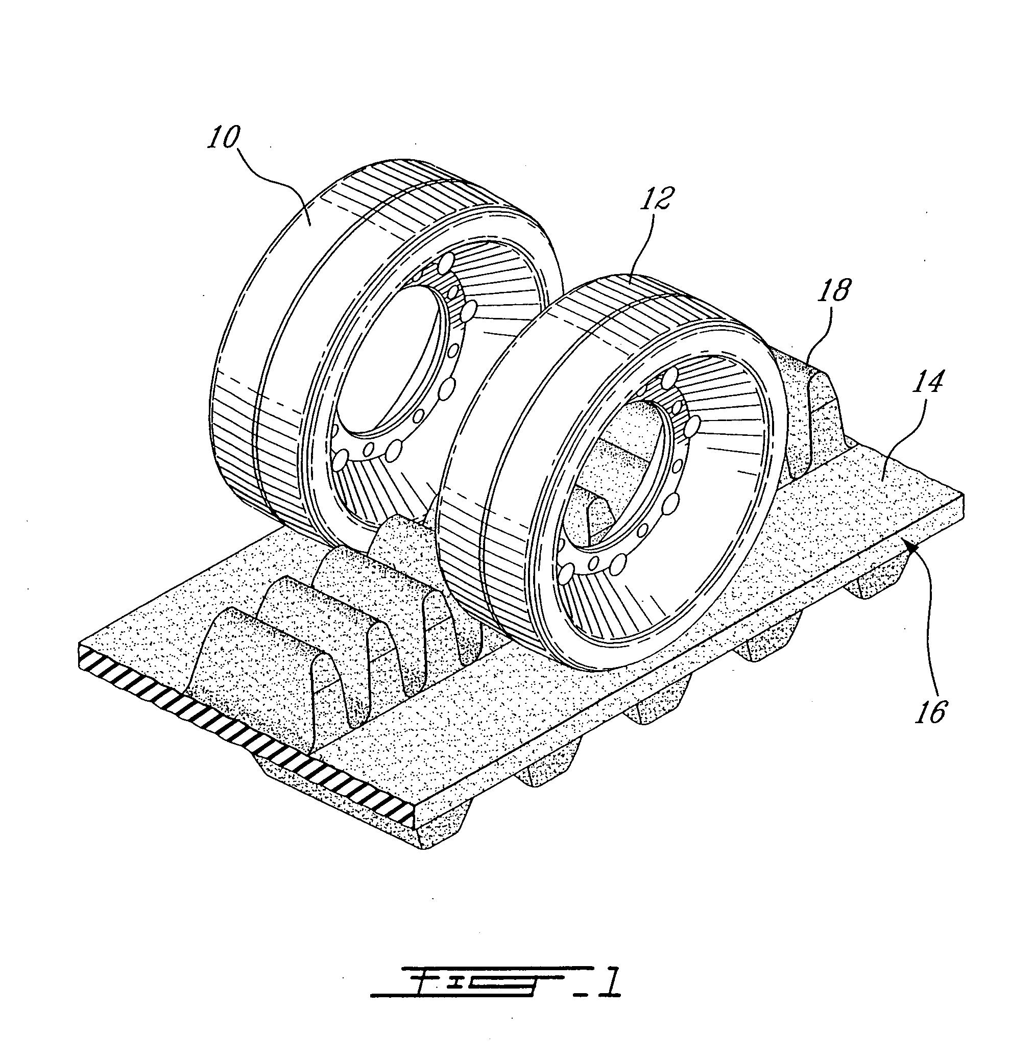
[0012]FIG. 1 shows a pair of mid-rollers 10 and 12 in contact with the inner surface 14 of an endless track 16. The inner surface of the track has a series of longitudinally spaced drive lugs 18 disposed centrally of the track. These drive lugs define a guiding path for the rotating track.

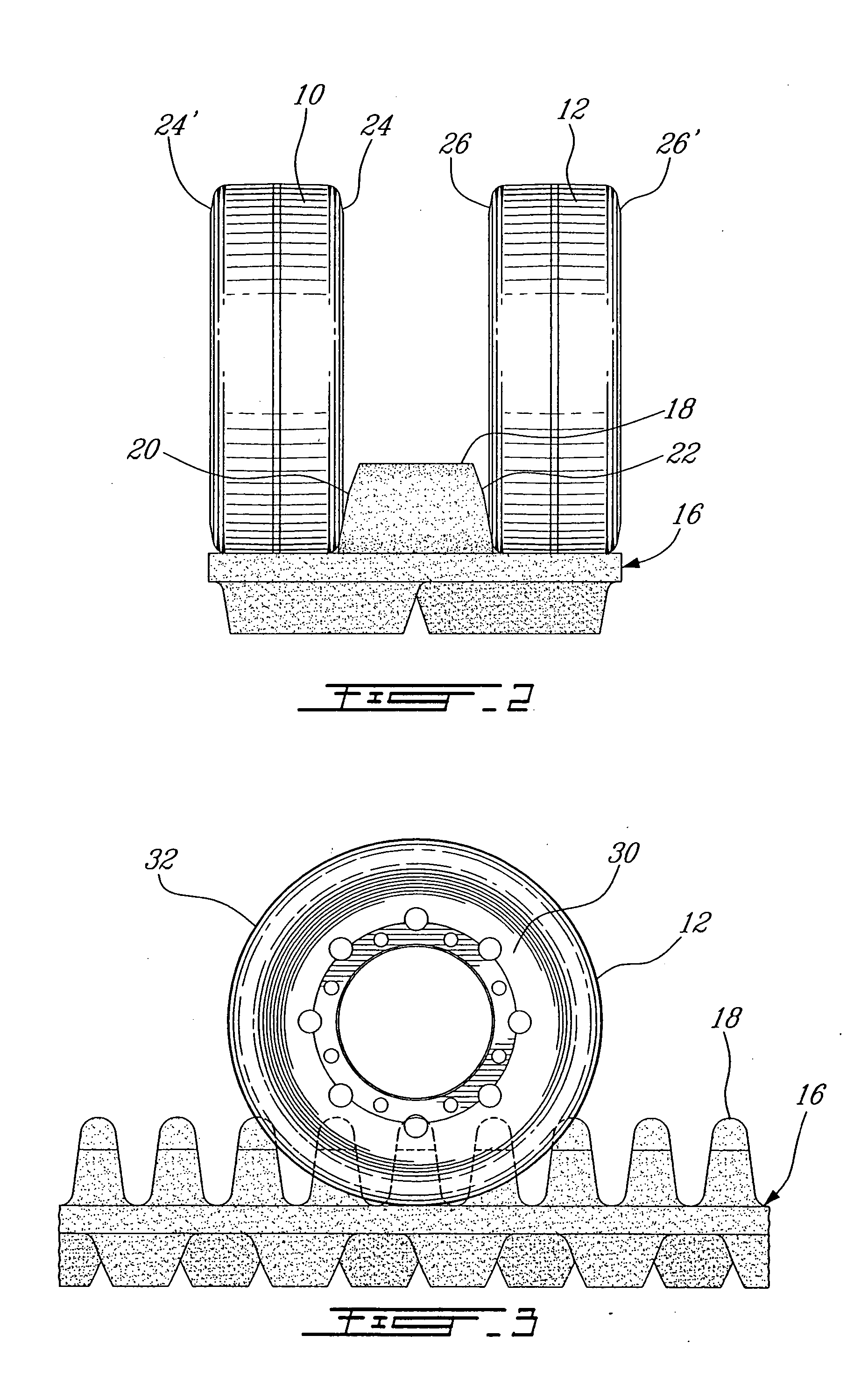
[0013] Referring to FIG. 2, each of the drive lugs 18 has a pair of opposite side faces 20 and 22 which are in contact with the inner circumferential edges 24 and 26 of the drive wheels 10 and 12.

[0014] Referring to FIG. 3, each mid-roller 12 includes an annular steel frame 30 which is adapted to be mounted to the drive track system. The annular steel member 30 is embedded in an annular band 32 made of a low friction material.

[0015] In a preferred form of the present invention, the construction of the mid-roller is symmetric so that, should the circumferential edges 24 and 26 be worn, the mid-rollers can be rotated so that their opposite peripheral edges 24′ and 26′ may now contact the side surf...


PUM


Abstract

The mid-rollers of an endless track assembly of a track-type vehicle contacting the inner surface of the track as well as drive lugs formed thereon are formed of a solid heat-resisting thermoplastic material having low friction properties in at least areas of the rollers exposed to the drive lugs.

Description

FIELD OF THE INVENTION [0001] The present invention pertains to the construction of mid-roller wheels which form part of the endless drive track system of track-type vehicles, such as agricultural, industrial or the like vehicle. BACKGROUND OF THE INVENTION [0002] Track-type vehicles have track assembly that usually includes an endless rubber belt which wraps around a drive wheel, an idler wheel and a number of mid-rollers. The inner surface of the endless belt has a number of extending guide lugs which are guided through a channel formed by the wheel arrangement. [0003] During use of the vehicle, the drive wheel rotates and engages the endless belt thereby causing the belt to rotate around the path defined by the drive wheel, idler wheel and mid-rollers. Rotation of the endless belt causes each of the guide lugs to pass through the channel defined by the drive wheel, idler wheel and each of the mid-rollers. Having the guide lugs passing through the guiding channel enables the belt ...

Claims


Application Information

Patent Timeline
IPC IPC(8): B62D55/14
CPCB62D55/14
Inventor LAVOIE, DENYSLUSSIER, ALAIN
Owner CAMOPLASY INC
Why Eureka
Try Eureka