Antenna for portable radio

a portable radio and antenna technology, applied in the direction of resonant antennas, antenna earthings, elongated active element feeds, etc., can solve the problems of deteriorating transmission reception performance, achieve improved gain, reduce the size and thickness of mobile radio equipment, and widen the band

Inactive Publication Date: 2005-05-19
PANASONIC CORP
View PDF14 Cites 14 Cited by
  • Summary
  • Abstract
  • Description
  • Claims
  • Application Information

AI Technical Summary

Benefits of technology

[0004] An object of the present invention is to reduce the size and thickness

Problems solved by technology

Therefore, there is a problem that the transmission reception p

Method used


Image

  • Antenna for portable radio
  • Antenna for portable radio
  • Antenna for portable radio

Examples


embodiment 1

(Embodiment 1)

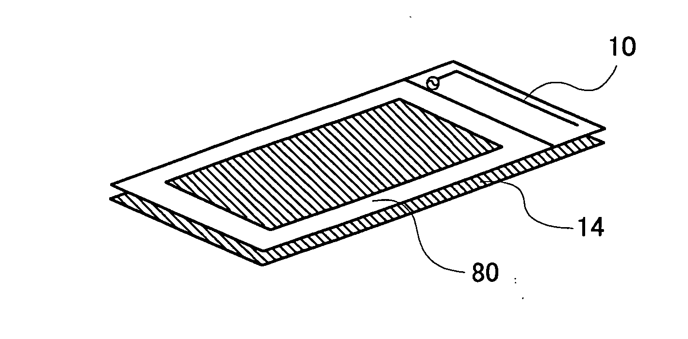
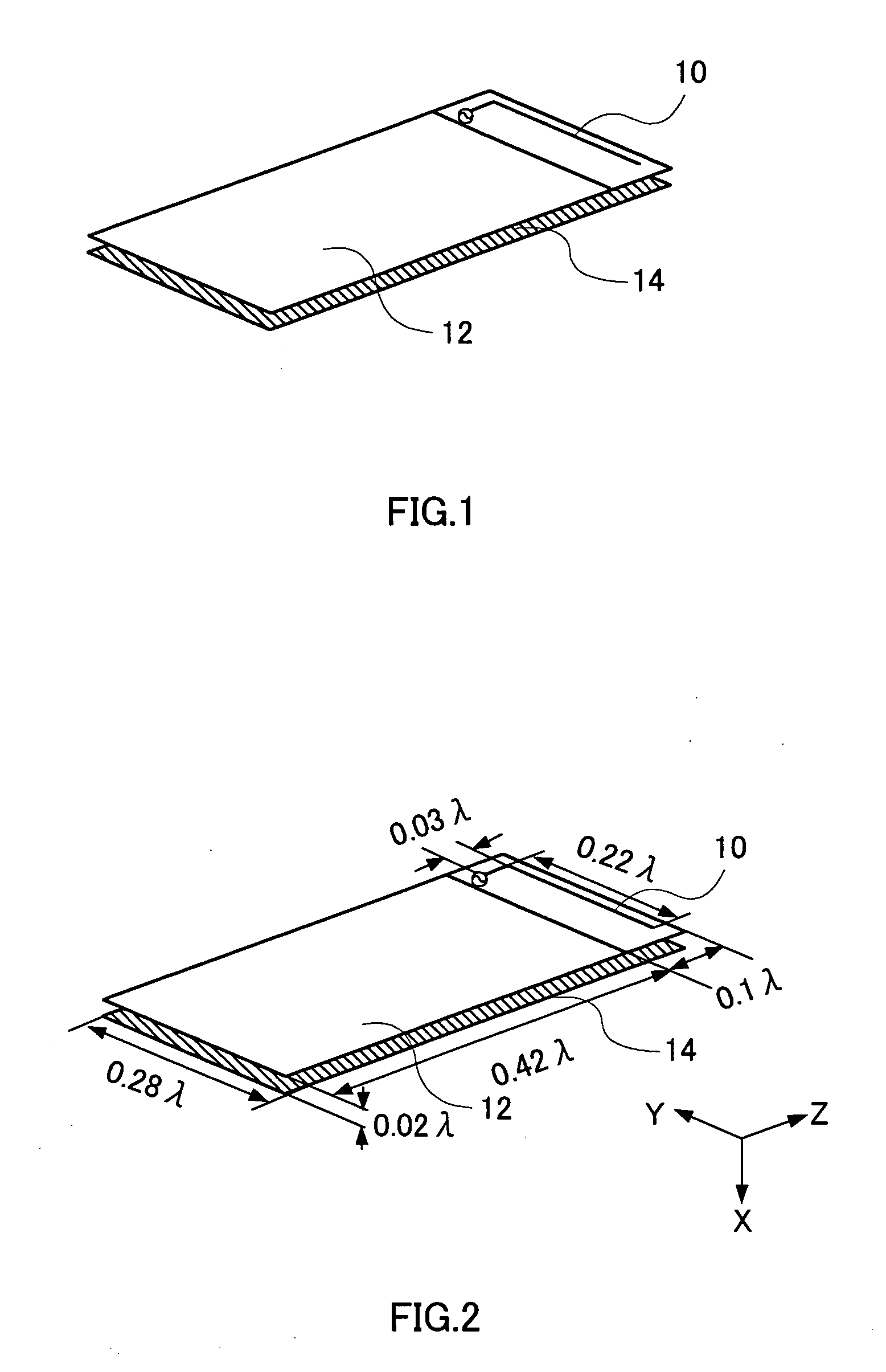
[0031]FIG. 1 is a view showing the configuration of a mobile radio apparatus antenna according to a first embodiment of the present invention. The mobile radio apparatus antenna shown in FIG. 1 is configured with a inverted-L antenna 10, a circuit board 12, and a planar antenna 14. The mobile radio apparatus antenna shown in FIG. 1 is built in a mobile radio apparatus.

[0032] The inverted-L antenna 10 is a feed element with one end thereof electrically connected to one of the plate surfaces of the circuit board 12 through a feed point. The inverted-L antenna 10 emits / absorbs radio waves.

[0033] The circuit board 12 is a circuit board of a mobile radio apparatus, to which circuit parts including the inverted-L antenna 10 are connected.

[0034] The planar antenna 14 is a parasitic element provided facing the backside plate surface of the plate surface of the circuit board 12 to which the inverted-L antenna 10 is connected, with an electrical length in the length direction...

embodiment 2

(Embodiment 2)

[0041] In the mobile radio apparatus antenna according to a second embodiment of the present invention, by meanderingly forming the feed element, the feed element is arranged on the circuit board of a predetermined dimension.

[0042]FIG. 4 is a view showing the configuration of the mobile radio apparatus antenna according to the second embodiment. The mobile radio apparatus antenna shown in FIG. 4 includes a meandering antenna 20 instead of the inverted-L antenna 10 of the mobile radio apparatus antenna shown in FIG. 1. The other parts are the same as those of the mobile radio apparatus antenna shown in FIG. 1, and so explanation is omitted here.

[0043] The meandering antenna 20 is a feed element with one end thereof electrically connected to one surface of the circuit board 12 through a feed point, and is an antenna element formed meanderingly. The meandering antenna 20 emits / absorbs radio waves.

[0044] The planar antenna 14 is connected to the meandering antenna 20 an...

embodiment 3

(Embodiment 3)

[0048] In the mobile radio apparatus antenna according to a third embodiment of the present invention, the inverted-L antenna is provided with a lumped constant, thereby adjusting the self-impedance of the inverted-L antenna.

[0049]FIG. 5 is a view showing the configuration of the mobile radio apparatus antenna according to the third embodiment. The portable radio apparatus antenna shown in FIG. 5 has a configuration in which the lumped constant 30 is loaded on the inverted-L antenna 10 of the portable radio apparatus antenna shown in FIG. 1. The other parts are the same as those of the mobile radio apparatus antenna shown in FIG. 1, and so explanation is omitted here.

[0050] The lumped constant 30 is loaded on the inverted-L antenna 10, and the self-impedance of the inverted-L antenna 10 is adjusted.

[0051] Here, by adjusting the dimension of the inverted-L antenna 10, the circuit board 12, and the planar antenna 14, and the distance therebetween, to predetermined val...


PUM


Abstract

A mobile radio apparatus antenna for improving the gain and widening the band is provided. A inverted-L antenna (10) is a feed element with one end thereof electrically connected to one plate surface of a circuit board (12) through a feed point. The circuit board (12) is a circuit board of a mobile radio apparatus, to which the circuit parts including the inverted-L antenna (10) are connected. A planar antenna (14) is provided facing the backside plate surface of the plate surface of the circuit board (12), to which the inverted-L antenna (10) is connected, and is a parasitic element with an electrical length in the length direction set to approximately ½ of the wavelength of radio waves communicated by the mobile radio apparatus. Here, the dimension of the inverted-L antenna (10), the circuit board (12), and the planar antenna (14), and the distance therebetween are adjusted to predetermined values, so as to change the self-impedance of the inverted-L antenna (10), the self-impedance of the planar antenna (14), and the mutual impedance between the inverted-L antenna (10) and the planar antenna (14).

Description

FIELD OF THE INVENTION [0001] The present invention relates to a mobile radio apparatus antenna. TECHNICAL FIELD [0002] In recent years, with the spread of communication apparatuses such as a mobile radio apparatus, further miniaturization is desired. Along with this, a built-in antenna is desired. Conventionally, typical example of this kind of an antenna apparatus is disclosed in Laid Open Japanese Patent Application No. 2001-244715. In order to prevent characteristic deterioration due to the influence of a human body, this antenna is designed to be a built-in antenna that causes no induced current on a radio circuit board by arranging a parasitic element above a feed element. [0003] However, this prior-art built-in antenna has directivity of large radiation in a direction of the human body. Therefore, there is a problem that the transmission reception performance deteriorates due to the influence of the human body. Moreover, in order to improve gain during call, it is preferable ...

Claims


Application Information

Patent Timeline
IPC IPC(8): H01Q1/24H01Q1/38H01Q9/04H01Q9/42H01Q11/04
CPCH01Q1/243H01Q1/38H01Q11/04H01Q9/42H01Q9/0442
Inventor KOJIMA, SUGURU
Owner PANASONIC CORP
Why Eureka
Try Eureka