
Apparatus and method of driving a plasma display panel

a plasma display and apparatus technology, applied in the field of apparatus and a method of driving a plasma display panel, can solve the problems of reducing the substantially applied voltage value of the panel, affecting the brightness and reliability of the panel, and affecting the stability of the panel, so as to prevent the power dispersion of the heavily-loaded horizontal line

Inactive Publication Date: 2005-05-19
LG ELECTRONICS INC
View PDF8 Cites 5 Cited by
  • Summary
  • Abstract
  • Description
  • Claims
  • Application Information

AI Technical Summary

Benefits of technology

The present invention provides a method and apparatus for driving a plasma display panel that can enhance the brightness difference between horizontal lines. This is achieved by detecting loads in data to be supplied to adjacent horizontal lines and correcting the data to be supplied to each line based on the load difference between them. This prevents power dispersion and ensures consistent brightness across the entire display.

Problems solved by technology

Namely, in case that the load of the panel is great, the voltage value substantially applied to the panel is lowered to bring about an unstable sustain discharge.
Hence, the brightness and reliability of the panel are degraded.
In doing so, since the brightness is corrected by computing the total one frame, it is unable to correct the brightness minutely.

Method used


Image

  • Apparatus and method of driving a plasma display panel
  • Apparatus and method of driving a plasma display panel
  • Apparatus and method of driving a plasma display panel

Examples


first embodiment

[0053]FIG. 5 is a block diagram of an apparatus for driving a plasma display panel according to a first embodiment of the present invention.

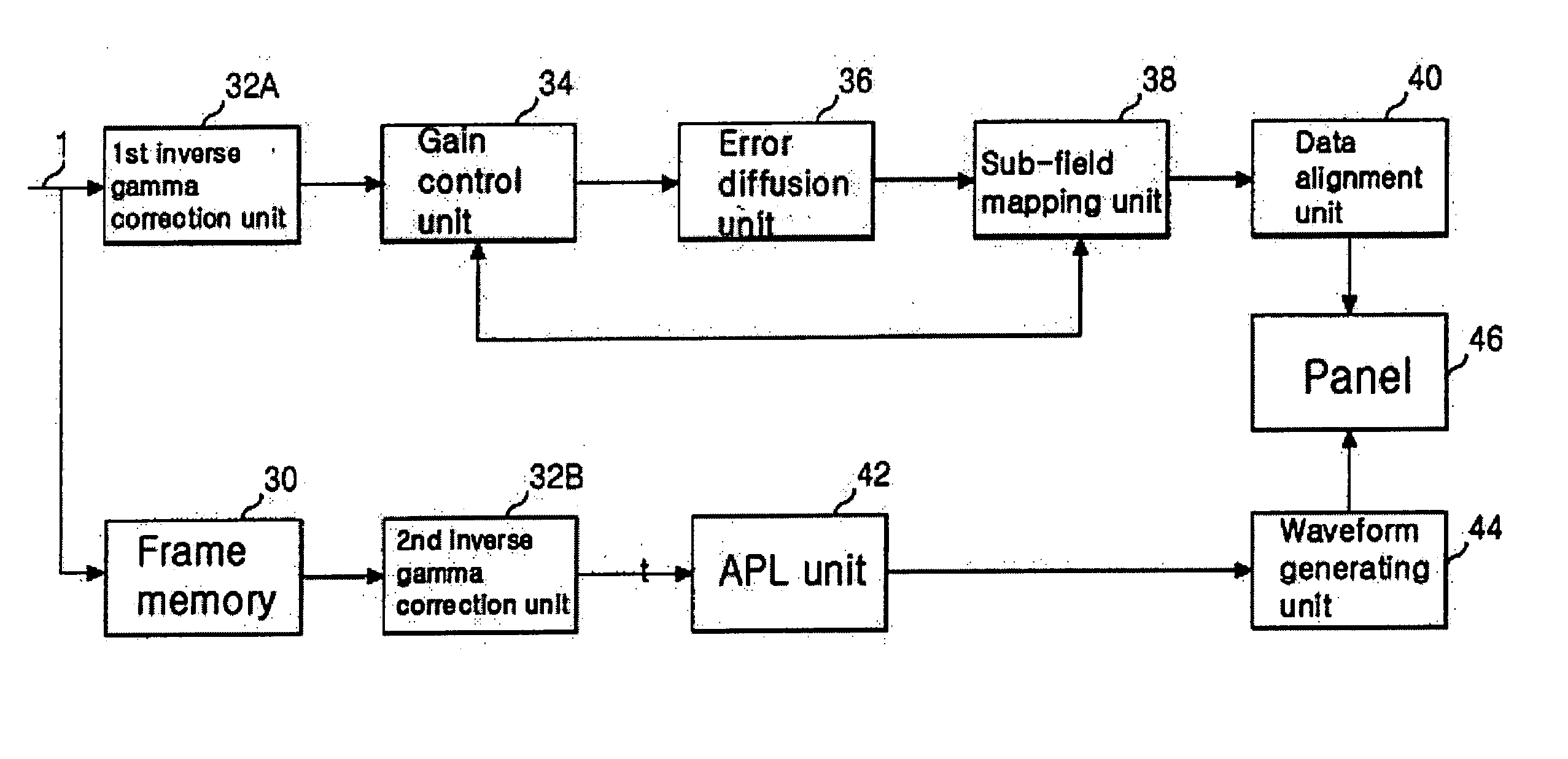
[0054] Referring to FIG. 5, an apparatus for driving a plasma display panel according to a first embodiment of the present invention includes a line buffer unit 110, comparison unit 112, data converting unit 120, first inverse gamma correction unit 132A, gain control unit 134, error diffusion unit 136, sub-field mapping unit 138, and data alignment unit 140 connected between an input line 101 and a panel 146. And, the apparatus according to the first embodiment of the present invention also includes a frame memory 130, second inverse gamma correction unit 132B, APL (average picture level) unit 142, and waveform generating unit 144 connected between the data converting unit 120 and the panel 146.

[0055] After having stored data of a kth horizontal line, the line buffer unit 110 synchronizes the data of the kth horizontal line and the data of a (...

second embodiment

[0071]FIG. 7 is a block diagram of an apparatus for driving a plasma display panel according to a second embodiment of the present invention.

[0072] Referring to FIG. 7, an apparatus for driving a plasma display panel according to a second embodiment of the present invention includes the same elements of the apparatus according to the first embodiment of the present invention shown in FIG. 5 except that first and second comparison units 112A and 112B are provided between a line buffer unit 110 and a data converting unit 120.

[0073] After having stored data of at least two horizontal lines, the line buffer unit 110 computes load values included in the data of the at least two horizontal lines and then supplies the load values to the first and second comparison units112A and 112B.

[0074] The first comparison unit 112A compares a first load value included in the data of a kth horizontal line and a second load value included in the data of a (k+1)th horizontal line to each other to deci...


PUM


Abstract

The present invention relates to a plasma display panel and, more particularly, to an apparatus and a method of driving a plasma display panel. According to the present invention, an apparatus for driving a plasma display panel includes a line buffer unit synchronizing data inputted from outside with a horizontal synchronization signal to store per horizontal line, at least one comparison unit comparing loads included in horizontal lines stored in the line buffer unit, and a data converting unit correcting the data to be supplied to the horizontal lines using a load difference resulting from a comparison by the at least one comparison unit. According to the present invention, a method of driving a plasma display panel includes the steps of detecting loads included in externally inputted data to be supplied to at least two adjacent horizontal lines and correcting the data to be supplied to each of the at least two adjacent horizontal lines according to a load difference between the at least two adjacent horizontal lines. Accordingly, the loads included in the previous and current lines are computed to correct the data to be supplied to the lines according to the load difference between the respective lines, respectively. Therefore, the present invention enables to correct the brightness difference between the horizontal lines and to prevent power dispersion of the heavily-loaded horizontal line.

Description

[0001] This Nonprovisional application claims priority under 35 U.S.C. § 119(a) on Patent Application No. 10-2003-0073311 filed in Korea on Oct. 21, 2003, the entire contents of which are hereby incorporated by reference. BACKGROUND OF THE INVENTION [0002] 1. Field of the Invention [0003] The present invention relates to a plasma display panel and, more particularly, to an apparatus and a method of driving a plasma display panel. [0004] 2. Description of the Background Art [0005] Generally, a plasma display panel (hereinafter abbreviated PDP) displays an image including characters and graphics in a manner of exciting a fluorescent substance by a 147 nm UV-ray emitted from a mixed gas discharge of (He+Xe), (Ne+Xe), or (He+Ne+Xe). PDP provides an excellent quality of image due to the recent development of technology as well as can be provided with a slim size and wide-screen. Specifically, a 3-electrodes AC surface discharge type PDP lowers its voltage necessary for an electric discha...

Claims


Application Information

Patent Timeline
Patent Type & Authority Applications(United States)
IPC IPC(8): H04N5/66G09F9/313G09G3/20G09G3/28G09G3/288G09G3/291G09G3/294G09G3/296G09G3/298H01J17/49
CPCG09G3/2059G09G3/2077G09G2360/16G09G2330/025G09G3/2944G09G3/296
Inventor LEE, JEUNG HWANCHUNG, MOON SHICKKOO, CHANG HWANSHIN, JUNG SUB
Owner LG ELECTRONICS INC
Learn More