Light guiding system, edge-type backlight module, and liquid display device

a liquid crystal display and light guiding technology, applied in the field of liquid crystal display technology, can solve the problems of affecting the function of components and the serious impact of the optical performance of the backlight module, and achieve the effects of enhancing the brightness difference on the light incident surface, reducing the amount of short wavelength and increasing the amount of visible lights entering the backlight modul

Inactive Publication Date: 2015-05-05
TCL CHINA STAR OPTOELECTRONICS TECH CO LTD
View PDF4 Cites 0 Cited by
  • Summary
  • Abstract
  • Description
  • Claims
  • Application Information

AI Technical Summary

Benefits of technology

[0025]In view of the above, the fluorescent film is arranged between the light emitting ends of the optical fibers and the light incident surface of the light guiding plate. In this way, light beams from the light emitting ends are diffused such that the brightness difference on the light incident surface is enhanced. In addition, as the fluorescent film is capable of converting the short wavelength lights to visible lights so that the amount of the short wavelength lights entering into the backlight module is decreased. In addition, the amount of the visible lights entering into the backlight module is increased. In this way, service life of the components within the liquid crystal display is increased.

Problems solved by technology

The optical performance of the backlight module may be seriously affected when the brightness differences are easily detected.
As many components of the backlight module are made by high-polymer materials, it is doubtless that the functions of components may be affected.

Method used


Image

  • Light guiding system, edge-type backlight module, and liquid display device
  • Light guiding system, edge-type backlight module, and liquid display device
  • Light guiding system, edge-type backlight module, and liquid display device

Examples


first embodiment

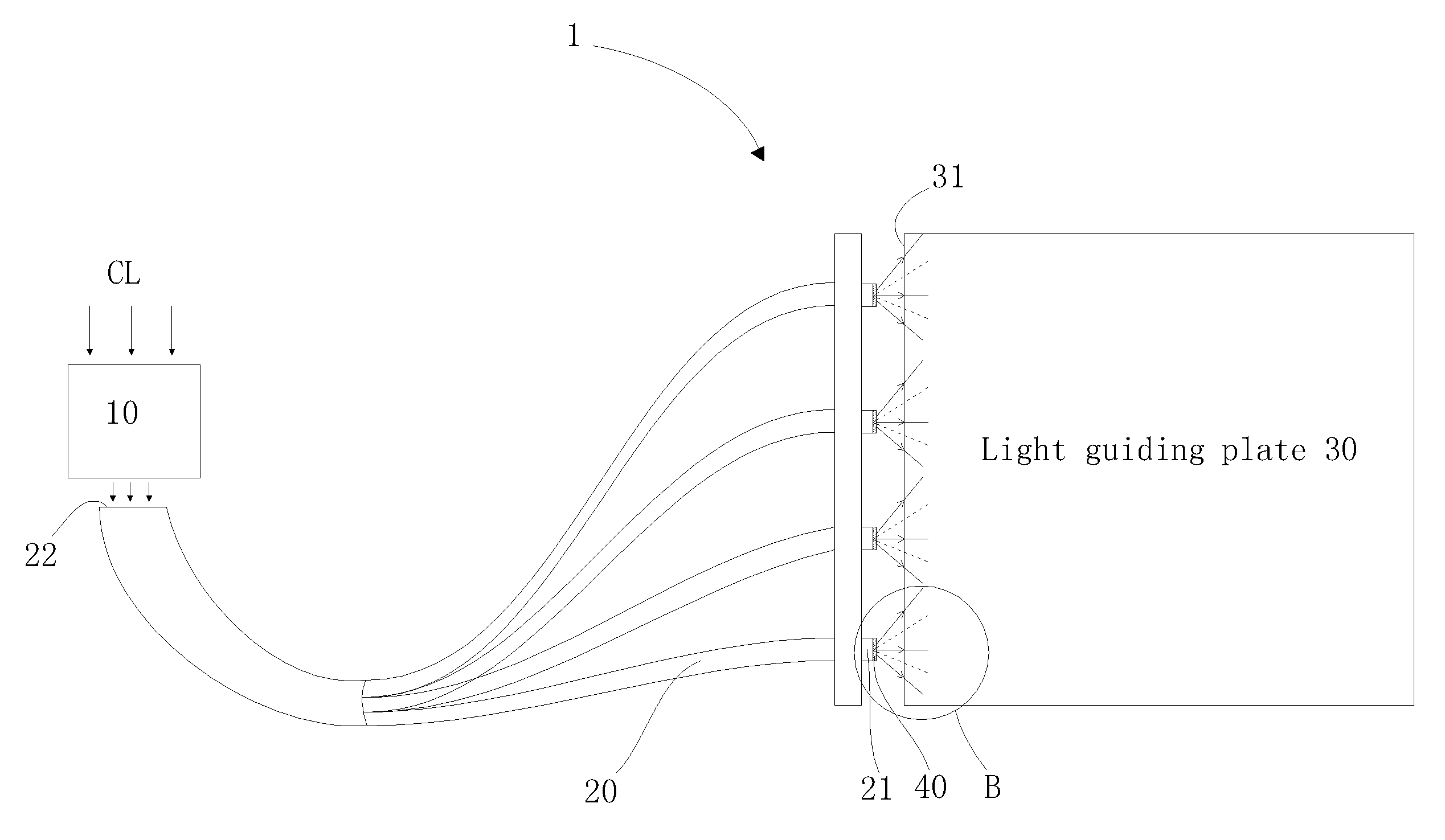
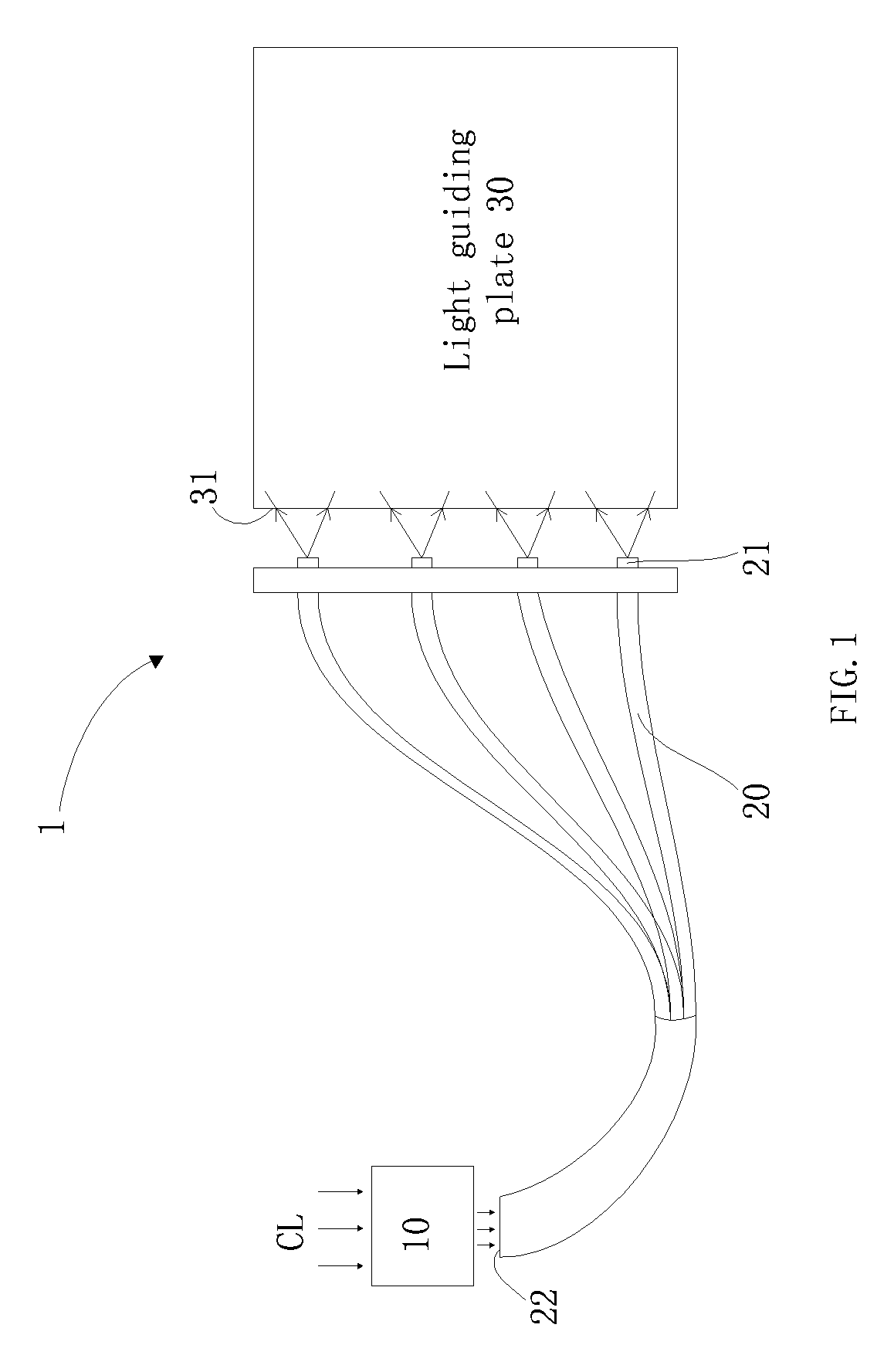
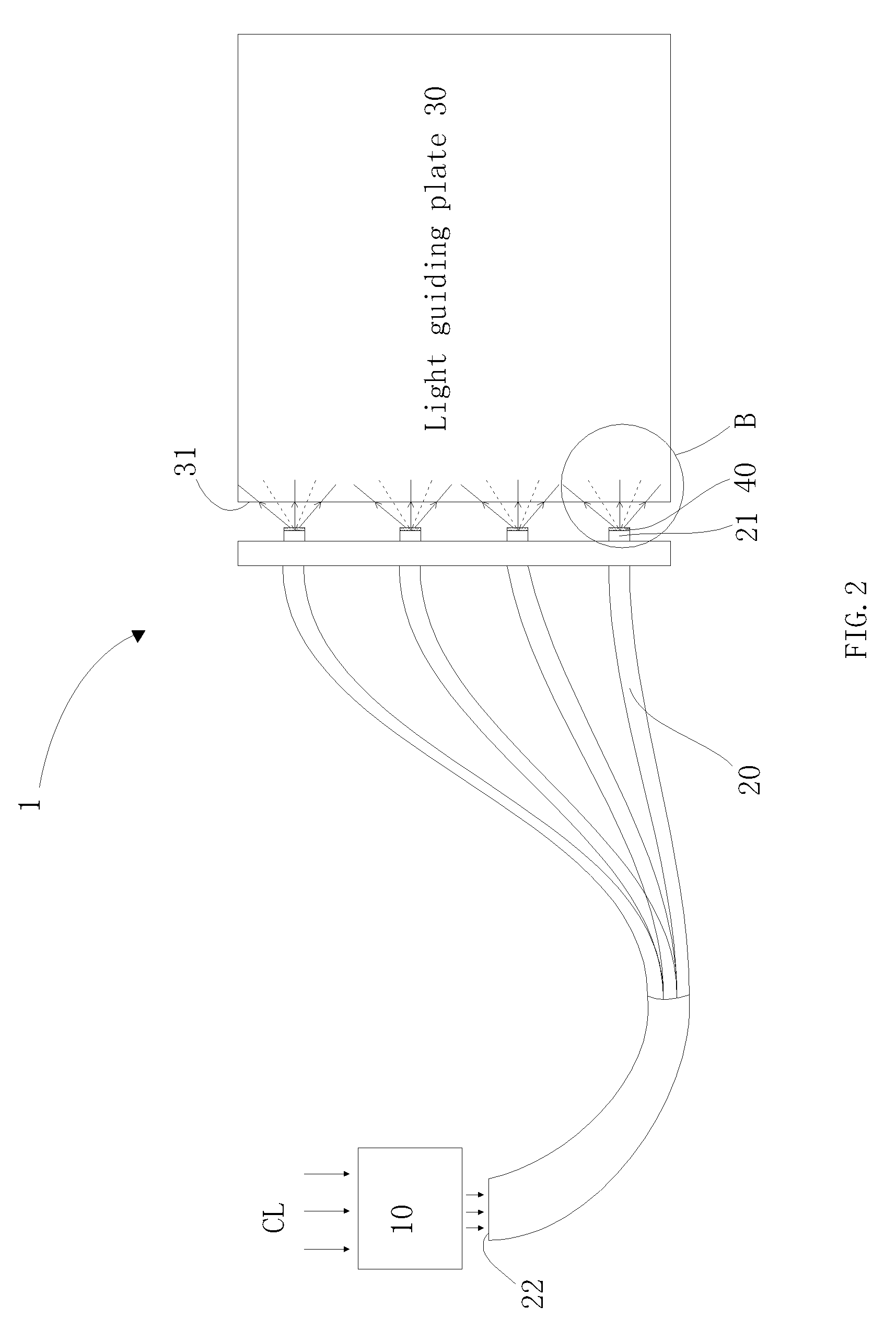
[0035]FIG. 2 is a schematic view of a light guiding system in accordance with a The light guiding system 1 includes an ambient light collection system 10, a plurality of optical fibers 20, and a fluorescent film 40. The ambient light collection system 10 faces toward the ambient light CL and absorbs the ambient light CL. It is to be noted that the ambient light CL may be sun lights, lamp lights, or lights radiated by other lighting objects. Each of the optical fibers 20 includes a light emitting end 21 and a light incident end 22. The light incident ends 22 of the optical fibers 20 are coupled together and are arranged close to the ambient light collection system 10. The light emitting ends 21 of the optical fibers 20 are arranged close to a light incident surface 31 of a light guiding plate 30. It is to be understood that the arrangement and the number of the light emitting ends 21 may be configured according to real scenarios. That is to say, the configuration of the light emitti...

second embodiment

[0039]FIG. 4 is a schematic view of the fluorescent film in accordance with a The fluorescent film 40 is arranged on the light incident surface 31 of the light guiding plate 30. The light beams 212, 213 have the optical paths as shown by the solid lines due to the diffusion particles in the fluorescent film 40. In this way, the lights emitted by the light emitting surface 211 are diffused.

third embodiment

[0040]FIGS. 5a and 5b are schematic views of the fluorescent film in accordance with a The fluorescent film 40 may be arranged on other positions. In one embodiment, a mask 90 is arranged in accordance to each of the light emitting ends 21. The mask 90 includes an internal wall 91 facing toward the light emitting end 21 and an outer surface 92 facing away the light emitting end 21. The fluorescent film 40 may be arranged on the internal wall 91 or the outer surface 92. The light beams 212, 213 have the optical paths as shown by the solid lines due to the diffusion particles in the fluorescent film 40. As such, the lights emitted from the light emitting surface 211 are diffused. It is to be noted that the shape of the mask 90 may be, but not limited to, substantially circle. The shape of the mask 90 may be rectangular or oval.


PUM

PropertyMeasurementUnit
light emitting angleaaaaaaaaaa
wavelengthaaaaaaaaaa

Abstract

A light guiding system, an edge-type backlight module and a liquid crystal display are disclosed. The light guiding system includes an ambient light collection system facing toward ambient light for absorbing the ambient light, a plurality of light guiding devices, and a fluorescent film arranged between the light emitting ends and the light incident surface. Each of the plurality of light guiding devices includes a light emitting end and a light incident end. The light emitting ends are arranged close to a light incident surface of a light guiding plate, and the light incident ends are arranged close to the ambient light collection system. The absorbed ambient light enters the light incident ends and propagates toward the light emitting ends. By adopting the fluorescent film, the light beams from the light emitting ends are diffused such that brightness difference on the light incident surface is enhanced.

Description

BACKGROUND OF THE INVENTION[0001]1. Field of the Invention[0002]Embodiments of the present disclosure relate to liquid crystal display technology, and more particularly to a light guiding system, an edge-type backlight module, and a liquid crystal display.[0003]2. Discussion of the Related Art[0004]Currently, original light sources are adopted as backlight sources in Liquid Crystal Displays (LCDs). The original light sources relate to light sources emitting lights by electrical power, such as LEDs. LEDs present many advantages including lower power consumption, and thus are broadly adopted as backlight sources. In order to reduce the impact toward environment, the power consumption of LEDs has to be further reduced. As such, the amount of adopted LEDs has to be decreased. Alternatively, an enhanced light source has to replace the typical ones.[0005]For example, ambient light is a new type of energy efficient solution without consuming electrical power is needed. One feasible solutio...

Claims


Application Information

Patent Timeline
Patent Type & Authority Patents(United States)
IPC IPC(8): G02F1/133F21V8/00G02F1/1335
CPCG02B6/0028G02B6/0068G02F1/133615G02B6/0023G02B6/0066
Inventor HU, CHE-CHANGHE, HU
Owner TCL CHINA STAR OPTOELECTRONICS TECH CO LTD
Why Eureka
Try Eureka