
Lensometers and wavefront sensors and methods of measuring aberration

a technology of wavefront sensors and lenses, applied in the direction of optical radiation measurement, refractometers, instruments, etc., can solve the problem that the correction optics provided on the basis of these sphere and cylinder measurements are often not suitable for correcting the vision of a person

Inactive Publication Date: 2005-05-19
ENTERPRISE PARTNERS VI
View PDF5 Cites 160 Cited by
  • Summary
  • Abstract
  • Description
  • Claims
  • Application Information

AI Technical Summary

Problems solved by technology

However, corrective optics provided on the basis of these sphere and cylinder measurements are often not suitable for correcting a person's vision.

Method used


Image

  • Lensometers and wavefront sensors and methods of measuring aberration
  • Lensometers and wavefront sensors and methods of measuring aberration
  • Lensometers and wavefront sensors and methods of measuring aberration

Examples


Embodiment Construction

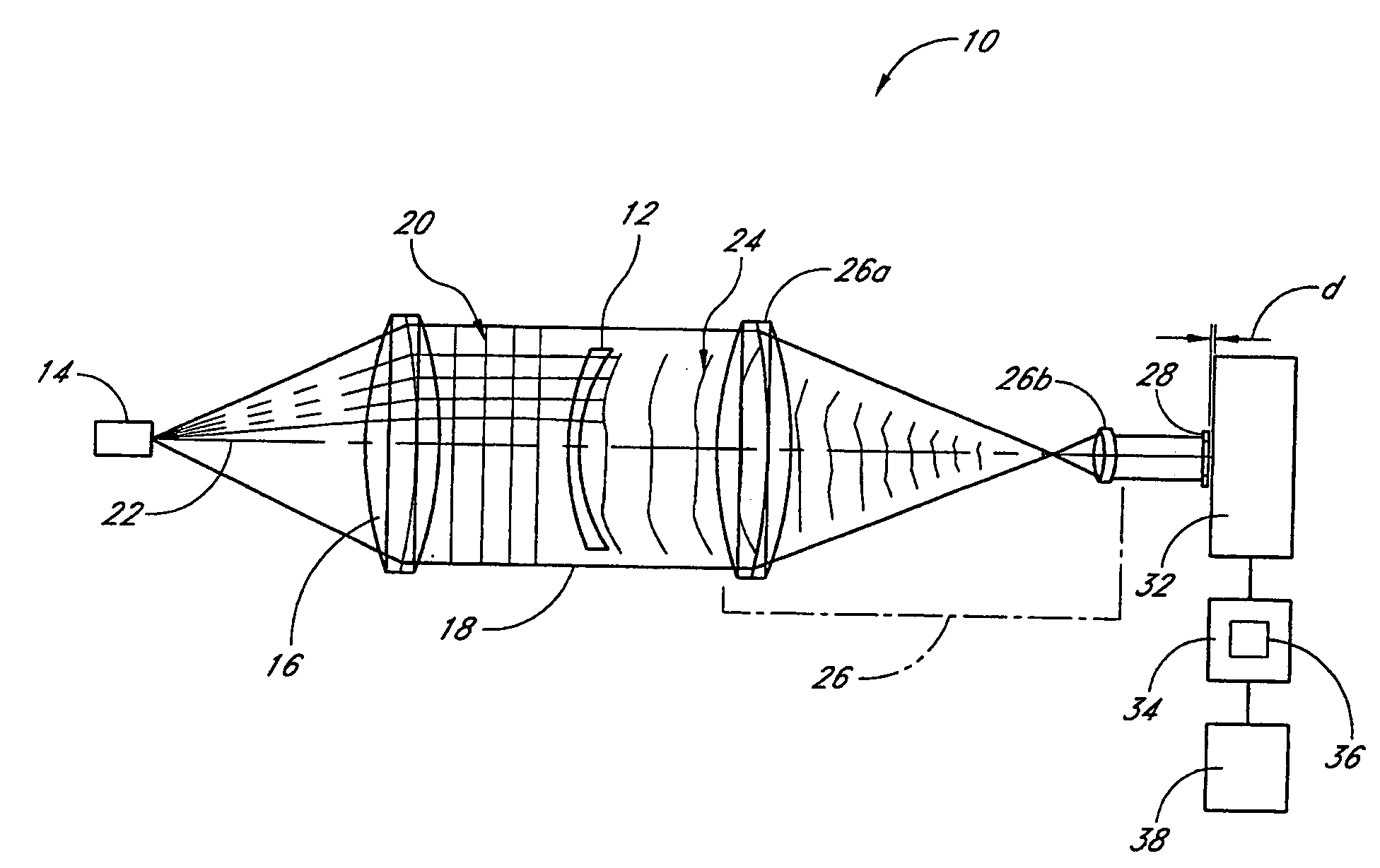
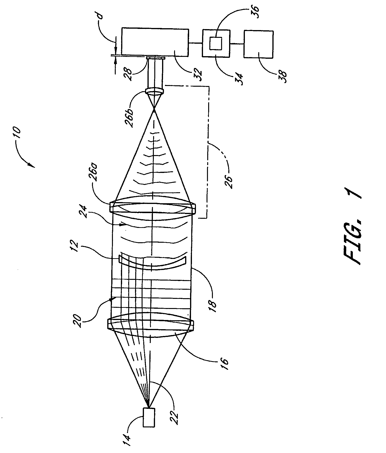
[0027]FIG. 1 depicts a lensometer 10, which is an optical system for measuring refractive or wave-shaping properties of a test lens 12. The lensometer 10 comprises a light source 14 such as a laser diode. The laser diode light source 14 preferably outputs light at a wavelength of about 550 nanometers (nm) although other wavelengths including infrared wavelengths may be employed to illuminate the test lens 12. Moreover, the laser preferably outputs a beam of light. The light is preferably substantially collimated, for example, preferably at less than about 30 arc seconds. Other types of lasers and light sources may be used for this purpose. In various preferred embodiments, the light source is semi-coherent.

[0028] The lensometer 10 further comprises beam tailoring optics, e.g., beam expanding and collimating optics 16 in the embodiment in FIG. 1. The beam expanding and collimating optics 16 may comprise one or more lenses or other optical elements configured to collect light emitted...


PUM


Abstract

Wavefront measuring systems and methods are disclosed which may be employed, for example, in detecting phase aberrations in a spectacle lens and in an eye. Various embodiments include disposing a modulation pattern in the path of a return beam from the spectacle lens or the eye, and imaging a diffraction pattern at a self-imaging plane relative to the modulation pattern with a detector. The diffraction pattern is analyzed and the results are used to produce a representation of the wavefront phase characteristics that describe aberrations in the lens or eye being measured. Illumination and processing techniques for improving the measurement results are dislcosed. Various embodiments comprise systems adaptable to both measure aberrations in lenses in spectacles as well as in a patient's eyes.

Description

PRIORITY APPLICATIONS [0001] This application claims the benefit of U.S. Provisional Application No. 60 / 520,294 entitled “Ophthalmic Diagnostic Instrument” (Attorney Docket No. OPH.024PR) filed Nov. 14, 2003, and U.S. Provisional Application No. 60 / 581,127, entitled “Lensometers and Wavefront Sensors and Methods of Measuring Aberration” filed Jun. 18, 2004, (Attorney Docket No. OPH.026PR), the entirety of which are incorporated herein by reference.FIELD OF THE INVENTION [0002] The invention relates generally to systems and methods for measuring wavefronts such as self-imaging based lensometers and wavefront sensors and methods of measuring aberrations of lenses such as corrective ophthalmic lenses as well as aberrations in the eye. BACKGROUND [0003] Traditional lensometers comprise an instrument used to determine the power and astigmatism (sphere and cylinder) of a spectacle lens. In particular, traditional lensometers comprise a centered telescopic optical system that includes a re...

Claims


Application Information

Patent Timeline
Patent Type & Authority Applications(United States)
IPC IPC(8): A61B3/103G01J9/00G01M11/02
CPCA61B3/1015G01M11/0235G01J9/00
Inventor WARDEN, LAURENCEFERRO, JOHNDREHER, ANDREAS W.FOOTE, WILLIAM G.
Owner ENTERPRISE PARTNERS VI
Learn More