

Bearing apparatus for a wheel of vehicle
a technology for vehicle wheels and bearings, which is applied in mechanical devices, rigid support of bearings, transportation and packaging, etc., can solve the problems of not only the knuckle 104, but the whole bearing, and it is difficult to disassemble the bearing from the knuckle 104, etc., to achieve disassembly and assembly, and achieve the effect of simple destructing only the stop ring
Inactive Publication Date: 2005-05-19
NTN CORP
View PDF9 Cites 35 Cited by
- Summary
- Abstract
- Description
- Claims
- Application Information
AI Technical Summary
Benefits of technology
The present invention provides a vehicle wheel bearing apparatus that is simple to assemble and disassemble, reducing manufacturing costs and man-hour. The apparatus includes an inner member with a wheel hub and inner rings fitted on axially extending cylindrical portions, and an outer member with double row rolling elements. An annular stop ring groove is formed on both the inner and outer members, and a predetermined shearing strength smaller than steel is fitted in the stop ring grooves. This allows for easy disassembly without causing damage to the knuckle and outer member. The stop ring is made of thermoplastic resin with chamfers for easy assembly. The inner rings are secured axially by a caulked portion, reducing weight, size, and manufacturing costs.
Problems solved by technology
However, in the prior art bearing apparatus, it is difficult to disassemble the bearing from the knuckle 104 to service the vehicle.
Thus, disassembly can never be achieved without destruction of the stop ring 106 which requires applying excess heavy load on the bearing.
Thus, it is impossible to reuse not only the knuckle 104 but the whole bearing.
Method used
View moreImage
Smart ImageViewing Examples

Examples
first embodiment
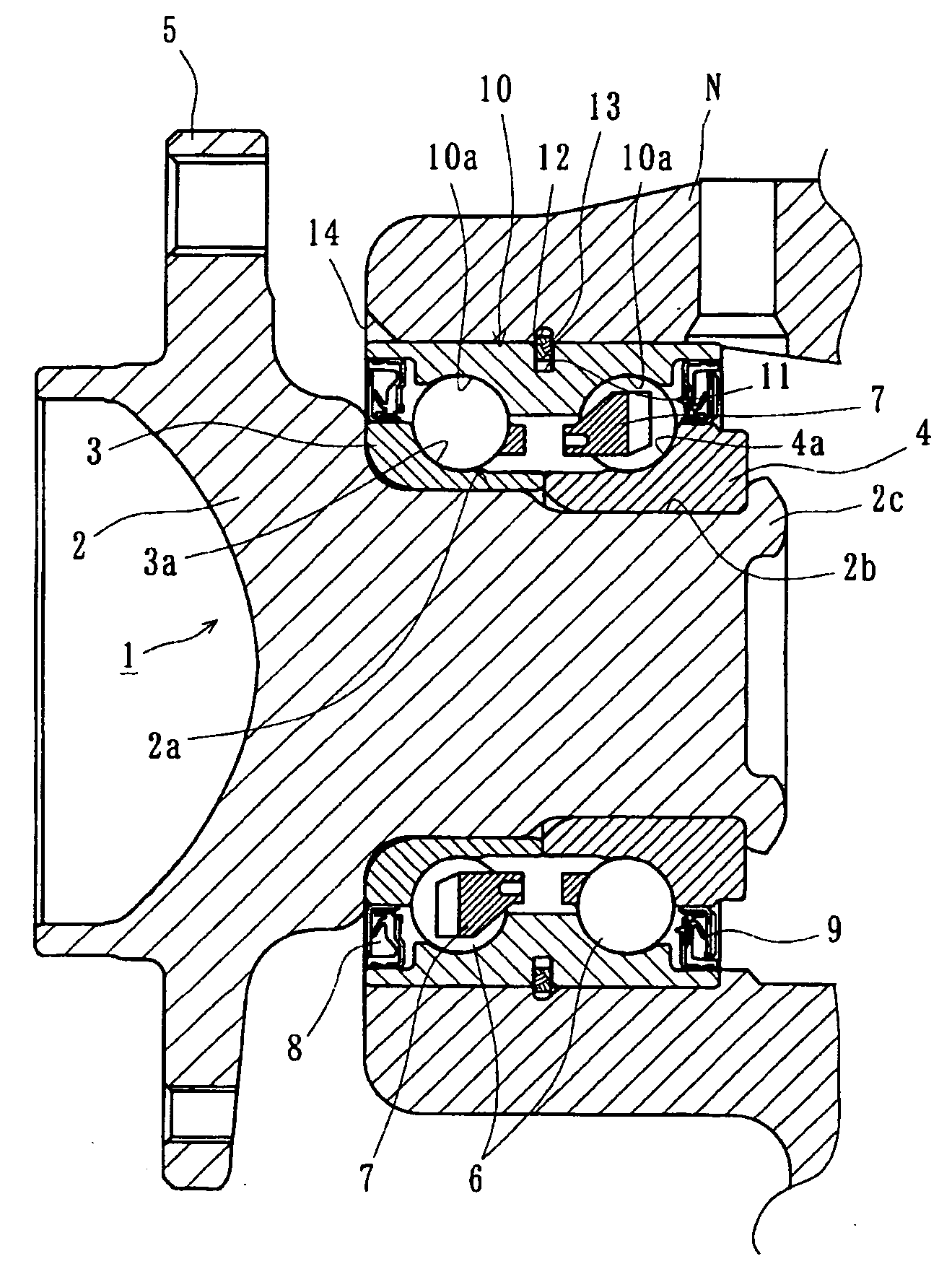
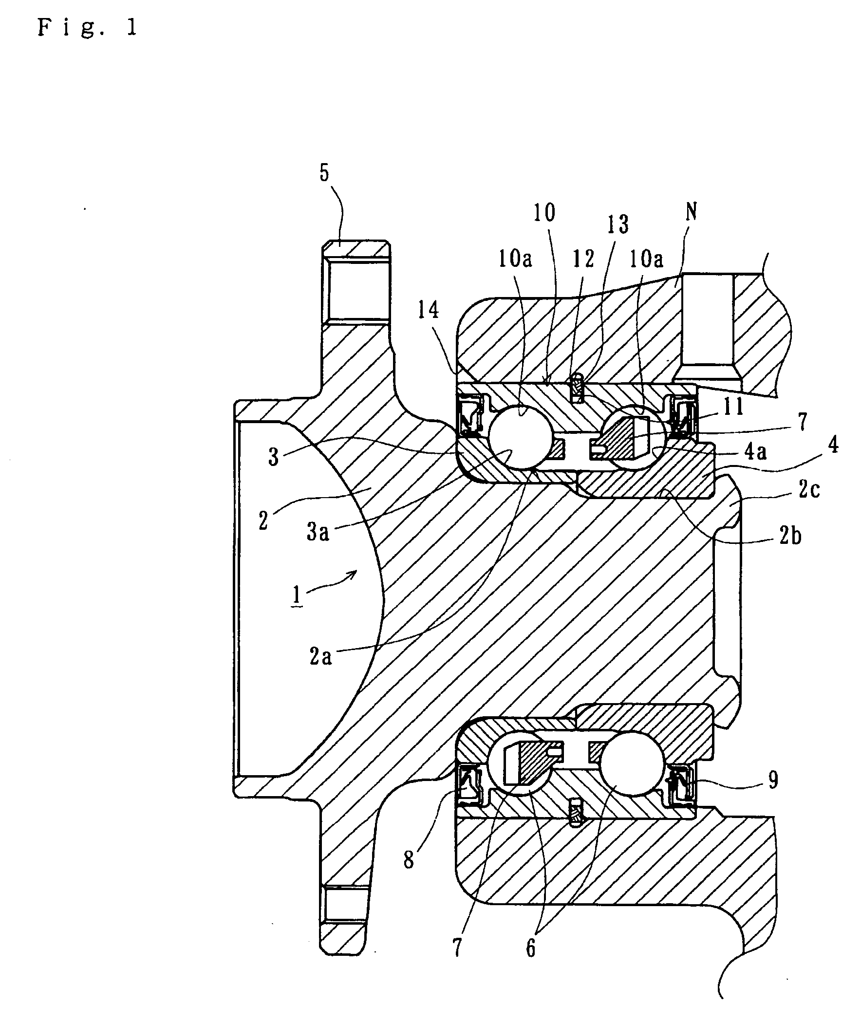
[0017]FIG. 1 is a longitudinal section view of a vehicle wheel bearing apparatus of the present invention;
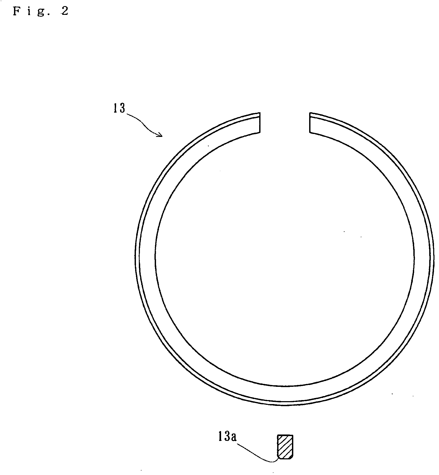
[0018]FIG. 2 is a front elevation view of a stop ring of the present invention;
second embodiment
[0019]FIG. 3 is a longitudinal section view of a vehicle wheel bearing apparatus of the present invention; and
[0020]FIG. 4 is a longitudinal section view of a vehicle wheel bearing apparatus of the prior art.
Login to View More PUM
 Abstract
A vehicle wheel bearing apparatus is simple to assemble and disassemble which reduces the man-hour in manufacturing and its manufacturing cost. The bearing apparatus has an inner member (1) including a wheel hub (2) integrally formed with a wheel mounting flange (5) at one end. Axially extending cylindrical portions (2a) and (2b) axially extend from the wheel mounting flange (5). Inner rings (3) and (4) are fitted on the axially extending cylindrical portions (2a) and (2b). An outer member (10) is fitted in a knuckle N which forms a part of a suspension apparatus. Double row rolling elements (6) and (6) are arranged between the inner and outer members (1) and (10). The wheel hub wheel, (2) is rotatably supported by the knuckle N. Annular stop ring grooves (11) and (12) are formed, respectively, on the outer circumferential surface of the outer member (10) and the inner circumferential surface of the knuckle N. A stop ring (13), with a predetermined shearing strength of 20˜200 MPa, is fitted in the stop ring grooves (11) and (12).
Description
CROSS-REFERENCE TO RELATED APPLICATIONS [0001] This application claims priority to Japanese Patent Application No. 2003-356325, filed Oct. 16, 2003, which application is herein expressly incorporated by reference. FIELD OF THE INVENTION [0002] The present invention relates to a bearing apparatus for a vehicle wheel that rotatably supports the wheel relative to a suspension apparatus of the vehicle and, more particularly, to an improvement of a mounting structure of the bearing apparatus for the vehicle wheel. BACKGROUND OF THE INVENTION [0003] Various types of vehicle wheel bearing apparatus have been used in which outer and inner rings are rotatably combined with each other vial rolling elements therebetween to rotatably support the wheel of the vehicle relative to the suspension apparatus. Also known is a vehicle wheel bearing apparatus as shown in FIG. 4. Here, an outer ring forms the bearing for a wheel that is mounted to a knuckle forming an independent suspension. [0004] The v...
Claims
Login to View More Application Information
Patent Timeline
 Patent Type & AuthorityApplications(United States)
IPC IPC(8): F16C35/077B60B27/00F16C19/18F16C33/58F16C35/067F16C43/04
CPCB60B27/00F16C2226/74F16C35/067F16C19/184F16C2326/02
InventorMURANAKA, MASAHIRONISHINO, KOJI
OwnerNTN CORP