Battery charger

a battery charger and charger body technology, applied in secondary cell servicing/maintenance, coupling device connection, transportation and packaging, etc., can solve the problems of increasing the size of the rotary shaft of the ac plug and the conductive spring terminal, and achieve the effect of gaining internal components, compact battery chargers, and effective preventing defective contacts

Inactive Publication Date: 2005-05-19
SONY CORP
View PDF6 Cites 6 Cited by
  • Summary
  • Abstract
  • Description
  • Claims
  • Application Information

AI Technical Summary

Benefits of technology

[0019] Moreover, there encounters another problem to increase the size of the rotary shafts of the AC plug and the conductive spring terminals due to increased distance between the two contact portions. As a result, a certain space is required at the periphery of the rotary shafts of the AC plug, thereby preventing miniaturization of the battery charger.
[0020] It is therefore an object of the present invention to provide a compact battery charger capable of constructing the peripheral portions of the rotary shafts of the AC plug with a smaller space while maintaining excellent connection.
[0022] According to the present invention, since contact portions for conductive blades are disposed on the respective surfaces of the rotary shafts at both sides of the AC plug in such a manner to slightly extend therefrom, it is possible to provide a more compact battery charger by constructing to have a smaller space at peripheral portions of the rotary shafts of the AC plug. It is also possible to effectively prevent defective contact due to displacement of the conductive spring terminals and the like because the protruding portions of the conductive spring terminals and the planar contact portions of the conductive blades make contact and the contact portions are disposed over a wider area.
[0023] Moreover, since the particular construction of the present invention is capable of minimizing the conductive spring terminals, it is possible to gain a space for internal components. Also, since freedom with regard to the shape of the conductive spring terminals is increased, compact design of the battery charger can be further enhanced. Furthermore, since unnecessary confirmation in assembling stages can be eliminated, it is possible to reduce manufacturing cost.

Problems solved by technology

Moreover, there encounters another problem to increase the size of the rotary shafts of the AC plug and the conductive spring terminals due to increased distance between the two contact portions.

Method used


Image

  • Battery charger
  • Battery charger
  • Battery charger

Examples


Embodiment Construction

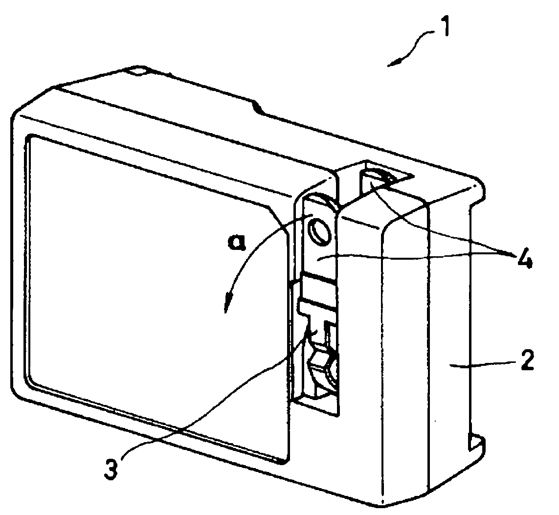
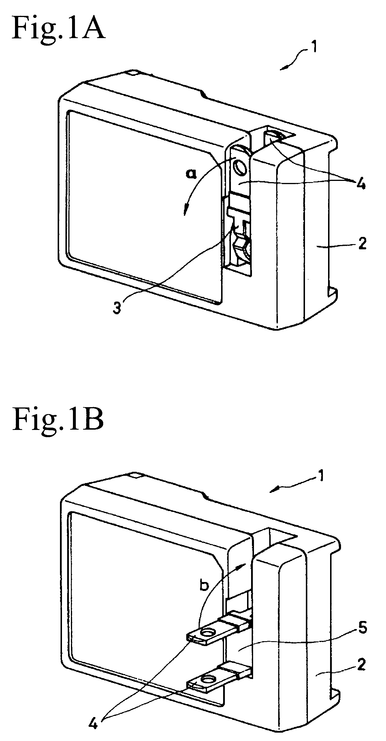
[0033] Now, a preferred embodiment of the present invention will be described hereunder by making reference to the accompanying drawings. FIGS. 1A and 1B are perspective views for illustrating an example of the battery charger according to embodiments of the present invention. FIG. 1A shows a condition where the AC plug 3 to be inserted into a wall outlet for an AC power source is accommodated inside the case 2 of the battery charger 1. The AC plug 3 has a pair of conductive blades 4 that project from the case 2 by being rotated at about 90 degrees in the direction of an arrow a (lateral rotation) about the rotary shafts of the AC plug 3. The battery charger is designed for charging, for example, a lithium ion battery to be used for a digital video camera, a digital still camera, or the like.

[0034] Shown in FIG. 1B is a condition where the AC plug 3 is rotated at about 90 degrees in the direction of the arrow a from the condition as shown in FIG. 1A so that the conductive blades 4 ...


PUM

PropertyMeasurementUnit
distanceaaaaaaaaaa
angleaaaaaaaaaa
distanceaaaaaaaaaa

Abstract

An AC adaptor has an AC plug having wider contact portions facilitating better contact despite the displacement. AC plug 3 of AC adaptor 3 has a pair of conductive blades 4, an end surface with the blades projecting with a substantially right angle, a first surface and a first rotary shaft on a first side surface. On a second side surface opposite to the first side surface, there are provided a second surface and a second rotary shaft. A first and second planar contact portions which are electrically connected respectively to a first and second conductive blades are configured respectively to project slightly from the surfaces of the first and second rotary shafts. On a circuit board in the case, there are provided conductive spring terminals 17 with projecting portions thereof making resilient contact with the first and second planar contact portions 15.

Description

CROSS REFERENCE TO RELATED APPLICATION [0001] This application claims priority from Japanese Priority Application No. 2003-385289, filed on Nov. 14, 2003 with the Japanese Patent Office, the entire content of which is hereby incorporated by reference. BACKGROUND OF THE INVENTION [0002] 1. Field of the Invention [0003] The present invention relates to a battery charger, more specifically to a battery charger having a rotary AC plug which can be accommodated in a case of the main body. [0004] 2. Description of Related Art [0005] In recent years, various types of portable machines including digital video cameras, digital still cameras and the like are well accepted by many generations and find wide applications. Power supplies for such portable machines are mostly batteries. In particular, in light of advanced battery technology and ever increasing users' conscious to recycling, many portable machines are designed to operate on rechargeable batteries (for example, lithium ion batteries...

Claims


Application Information

Patent Timeline
Patent Type & Authority Applications(United States)
IPC IPC(8): H02J7/00H01M10/44H01R35/04
CPCH01R35/04
Inventor SAKAI, YOSHIHIRO
Owner SONY CORP
Why Eureka
Try Eureka