Seismic braces including pin and collar connection apparatus

a technology for connecting apparatuses and seismic braces, applied in the direction of shock-proofing, couplings, rod connections, etc., can solve the problems of consuming a significant portion of the fixed distance between the connection locations of the brace, and achieve the effect of facilitating hinged movement, preventing weak axis buckling of the core, and being simple and fas

Inactive Publication Date: 2005-05-26
COREBRACE LLC
View PDF1 Cites 34 Cited by
  • Summary
  • Abstract
  • Description
  • Claims
  • Application Information

AI Technical Summary

Benefits of technology

[0014] The knife plates of the brace-side member are secured in place relative to a load-bearing member, or “core,” of a seismic brace. For example, the knife plates may be welded directly to the core or to an intermediate member which is, in turn, welded to the core. These arrangements facilitate the positioning of an end of a yielding core closer to the structural steel frame than do conventional, rigid connections, which typically consume a significant portion of the fixed distance between brace connection locations. Thus, connection apparatus according to the present invention may facilitate the use of seismic braces which include yielding cores that are longer than the yielding cores of conventional seismic braces that may be used at the same location of a structural steel frame. As is well known in the art, an increase in the length of a yielding core means that the strain rate on the yielding core will be less, resulting in a fatigue life which is longer than the fatigue life of a similar brace secured at a similar location using conventional, rigid connection apparatus.
[0018] Of course, other arrangements and configurations of apparatus for connecting seismic braces to steel structural frames are also within the scope of the present invention. For example, another embodiment of connection apparatus that incorporates teachings of the present invention may comprise a ball-and-socket type connection apparatus. The first member, or frame-side member, of such a connection apparatus, which is securable to a steel structural frame, may comprise a socket. The socket may, for example, be in the form of an aperture with a concave edge. The coupling member of such a connection apparatus may comprise a ball, which may be spherical in shape, an oblong spheroid, disc-shaped, or otherwise configured to fit within the socket of the frame-side member and rotate somewhat relative to the frame-side member. The coupling member may also include one or more pins protruding from opposite sides thereof. The second member, or brace-side member, of a ball-and-socket type connection apparatus includes a pair of substantially planar members which are spaced apart a sufficient distance that the ball of the coupling member may be positioned therebetween. An aperture formed through each substantially planar member is configured to receive a portion of a pin protruding from the ball and, thus, facilitates hinged movement of the brace-side member and of a seismic brace to which the brace-side member is secured relative to one or both of the ball and the frame-side member of the connection apparatus.
[0019] In use, the frame-side member of a connection apparatus of the present invention is secured to a steel structural frame, such as in a corner formed between conjoined horizontal beams and vertical steel columns. Continuing with the above examples, this may be effected by welding or otherwise securing one or more gusset plates into such a corner. The brace-side member of the connection apparatus, which, preferably, has already been secured to or formed at the end of a core of a seismic brace, is then positioned appropriately relative to the frame-side member, such that apertures of the frame-side and brace-side members are substantially mutually aligned. A coupling member is then introduced into the aligned apertures so as to be positioned within each of the substantially aligned apertures of the frame-side and brace-side members. The coupling member is then secured in this position to prevent inadvertent removal thereof from the apertures. The opposite end of the seismic brace may then be similarly secured to another (higher or lower) horizontally extending steel beam. Alternatively, another type of connection, including a rigid, conventional connection, may be used to secure the other end of the seismic brace to the other horizontally extending beam. As a single pin is secured in position rather than several bolts, as required by conventional, rigid connection apparatus, erection of a seismic brace that includes a connection apparatus according to the present invention is simpler and faster than erection with conventional, rigid connection apparatus.
[0020] When a building that includes a frame with one or more seismic braces connected thereto by way of a connection apparatus of the present invention is subjected to a load, such as that generated by shock waves (e.g., seismic shock waves, high winds, etc.), the connection apparatus and the adjacent end of the seismic brace are substantially isolated from external moments that result from movement of the seismic brace out of the plane of the bay of a steel structural frame in which the seismic brace is located. The collar resists in-plane and out-of-plane moments on the exposed portions of the core of the seismic brace, as well as of the remainder of the connection apparatus, thereby permitting only substantially axial loads to be applied to the core, providing support to the core and the remainder of the connection apparatus, and preventing weak axis buckling of the core. In addition, the connection apparatus reduces the moments and shears that result from the application of gravity and earthquake loads to a steel structural frame by providing a larger moment of inertia at the ends of the core of a seismic brace. As a result, the connection element substantially limits the forces that are applied to the seismic brace to those which may be properly absorbed thereby.
[0021] As a further result of providing a nonrigid connection, the likelihood of a connection apparatus according to the present invention being damaged when subjected to gravity and earthquake loads is much lower than the likelihood of a conventional rigid connection being damaged. Thus, following failure due to absorption of excessive earthquake loads, a seismic brace which is at least partially secured to a steel structural frame by way of one or more of the inventive connection apparatus may still have some load-bearing capabilities and, thus, provide some structural support to a steel structural frame, whereas seismic braces that are secured in place by weakened conventional rigid connections would be less likely to provide such support.

Problems solved by technology

These arrangements facilitate the positioning of an end of a yielding core closer to the structural steel frame than do conventional, rigid connections, which typically consume a significant portion of the fixed distance between brace connection locations.

Method used


Image

  • Seismic braces including pin and collar connection apparatus
  • Seismic braces including pin and collar connection apparatus
  • Seismic braces including pin and collar connection apparatus

Examples


Embodiment Construction

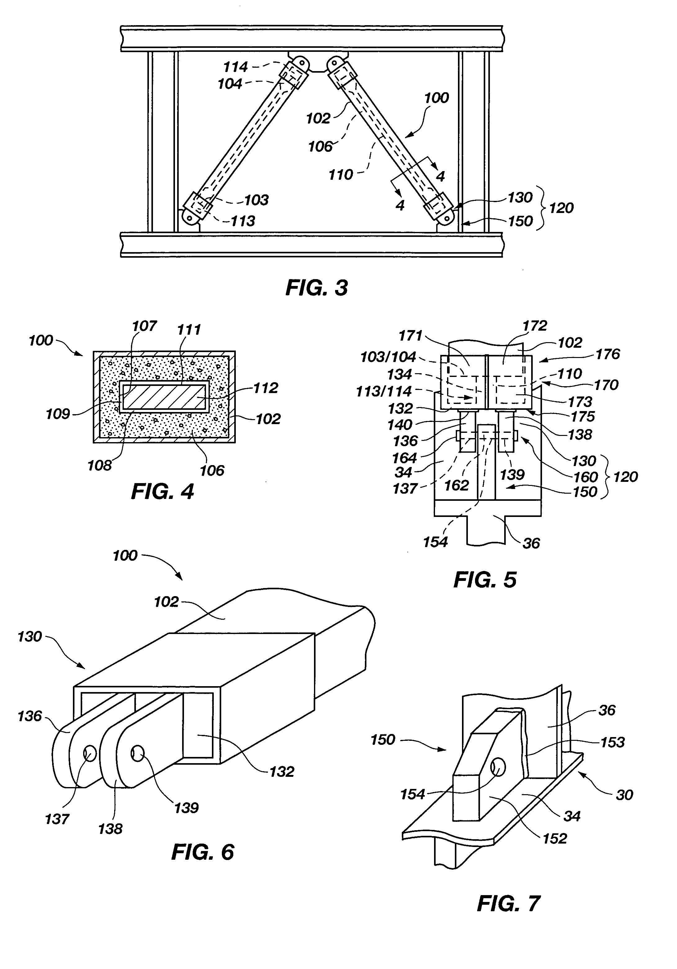
[0045] With reference to FIGS. 3 and 4, a seismic brace 100 that incorporates teachings of the present invention is depicted. In the illustrated example, seismic brace 100 is a single-core, compression and tension member which includes an elongate, substantially hollow exterior shell 102, a buckling-limiting member, which is also referred to herein as “containment 106,” within exterior shell 102, and an elongate yielding core 110 positioned substantially centrally within and extending completely along the length of containment 106. The depicted yielding core 110 has a rectangular, somewhat planar cross-section, taken transverse to the length thereof, and includes ends 113 and 114 which extend beyond corresponding ends 103, 104 of exterior shell 102. Yielding core110 is positioned within an aperture 108 that extends substantially through containment 106 and includes at least one surface 111 which is spaced apart from an interior surface 107 of containment 106 by way of a readily comp...


PUM


Abstract

A connection apparatus includes a frame-side member securable to a steel structural frame, a brace-side member securable to a seismic brace, and a coupling element that secures frame-side and brace-side members to each other. By way of example, the connection element may provide a hinge-type connection, which substantially isolates a seismic brace from nonaxial loads. As another example, the connection element may be a ball-and-socket type connection, which substantially isolates a seismic brace from nonaxial loads and absorbs any shear and moment applied thereto when the seismic brace drifts out of an intended plane of the steel structural frame. The connection element may also include a collar to stabilize the brace-side member and prevent shears and moments from causing the same to buckle in an unintended direction. Methods of installing and using the connection apparatus are also disclosed.

Description

CROSS-REFERENCE TO RELATED APPLICATION [0001] This application is a continuation of application Ser. No. 10 / 310,692, filed Dec. 5, 2002, now U.S. Pat. No. 6,837,010, issued Jan. 4, 2005.BACKGROUND OF THE INVENTION [0002] 1. Field of the Invention [0003] The present invention relates generally to connection apparatus for use with seismic braces. In particular, the present invention relates to connection apparatus which prevent seismic and gravitational loads on steel structural frames from being applied nonaxially to seismic braces. By way of example, the connection apparatus may allow the brace to pivot relative to a structural frame. [0004] 2. Background of Related Art [0005] In many areas of the world, particularly seismically active areas, large buildings and other structures may be subjected to seismic loads. In order to prevent structures from being damaged by seismic loads, particularly the vibrations that follow the application of seismic loads to structures, or to at least r...

Claims


Application Information

Patent Timeline
Patent Type & Authority Applications(United States)
IPC IPC(8): E04H9/02
CPCE04H9/02E04H9/028Y10T403/44F16C11/045Y10T403/345E04B2001/5868E04H9/0237
Inventor POWELL, STEVEN D.JOHNSON, ARGAN N. JR.RANDALL, DENNIS F.
Owner COREBRACE LLC
Why Eureka
Try Eureka