Heat exchanger package with split radiator and split charge air cooler

a heat exchanger and radiator technology, applied in indirect heat exchangers, machines/engines, lighting and heating apparatus, etc., can solve the problems of large performance loss of heat exchanger packages of fig. 1, inability to go into normal production, and inability to achieve good heat transfer performance, etc., to achieve low frontal area and high heat transfer performance

Inactive Publication Date: 2005-05-26
THERMAL SOLUTIONS MFG INC
View PDF20 Cites 25 Cited by
  • Summary
  • Abstract
  • Description
  • Claims
  • Application Information

AI Technical Summary

Benefits of technology

[0010] Bearing in mind the problems and deficiencies of the prior art, it is therefore an object of the present invention to provide a combination radiator and charge air cooler which achieves high heat transfer performance with a minimal frontal area.

Problems solved by technology

Notwithstanding its novel design, the heat exchanger package of FIG. 1 did not achieve good performance and did not go into normal production, to the inventor's knowledge.
It has now been determined that the performance of the heat exchanger package of FIG. 1 suffered in large part due to excessive charge air pressure drop through the two charge air cooler units.
However, higher power output requires increased cooling capacity.
This need for increased cooling capacity poses a dilemma for truck builders that have recently invested heavily in aerodynamic styling for their trucks.
The sloping hoods of new trucks seen on the highway today are a result of this restyling, which places extreme limitations on the size of the engine cooling package.

Method used


Image

  • Heat exchanger package with split radiator and split charge air cooler
  • Heat exchanger package with split radiator and split charge air cooler
  • Heat exchanger package with split radiator and split charge air cooler

Examples


Embodiment Construction

[0075] In describing the preferred embodiment of the present invention, reference will be made herein to FIGS. 2-23 of the drawings in which like numerals refer to like features of the invention.

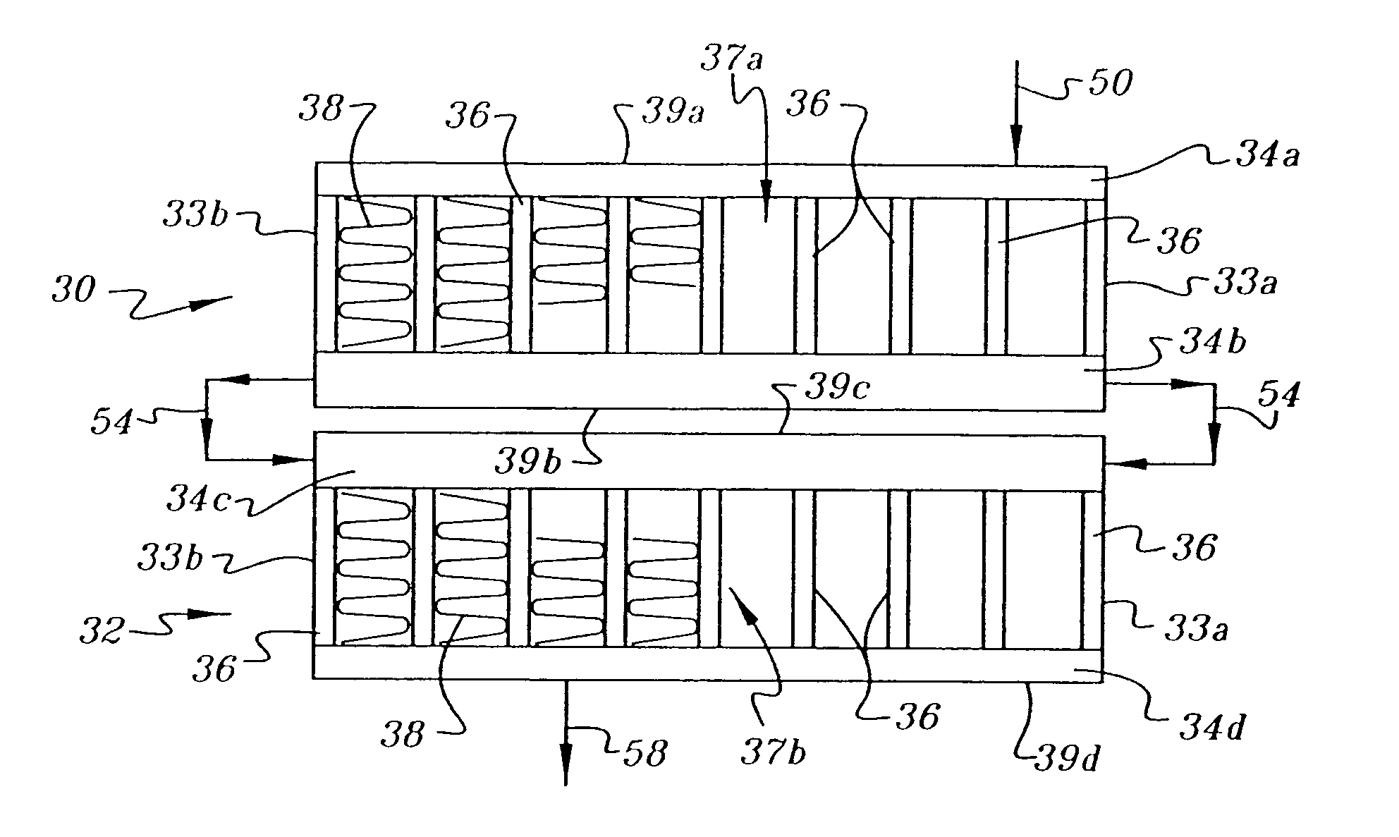
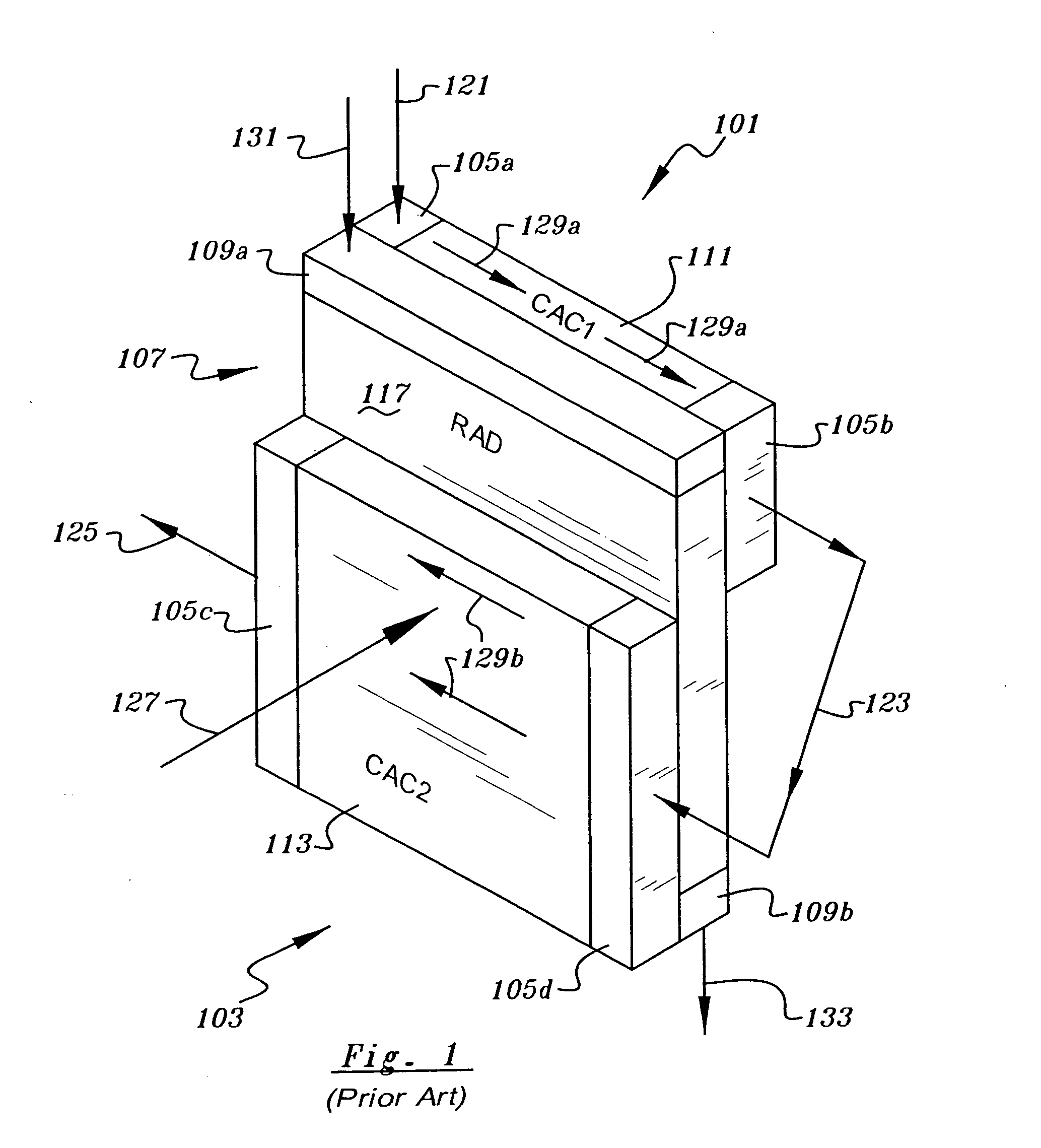
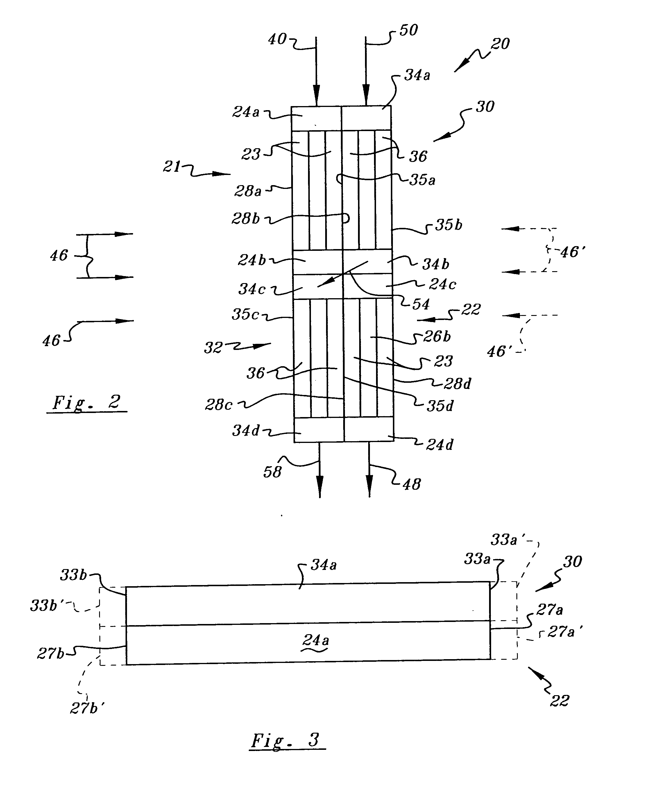
[0076] The preferred embodiment of the present invention is a cooling package utilizing a radiator in two portions and a charge air cooler (CAC) in two portions. The charge air cooler is arranged so that the entering hot charge air is directed into the first portion of the charge air cooler, which is located downstream in the direction of cooling air flow from the first portion of the radiator. The partially cooled charge air exiting the first portion of the charge air cooler is then directed into the second portion of the charge air cooler, which is located upstream in the direction of cooling air flow from the second portion of the radiator. In this way, the exiting charge air is cooled by the coolest cooling air. To minimize charge air pressure drop through the charge air cooler portions...


PUM


Abstract

A combined radiator and charge air cooler package includes a radiator having upper and lower portions for cooling engine coolant and a charge air cooler having upper and lower portions for cooling charge air. The upper charge air cooler portion is disposed in overlapping relationship and adjacent to the upper radiator portion, and the lower charge air cooler portion is disposed in overlapping relationship and adjacent to the lower radiator portion. The upper radiator portion and the lower charge air cooler portion are aligned in a first plane, and the lower radiator portion and the upper charge air cooler portion are aligned in a second plane, behind the first plane. Ambient cooling air may flow in series through the upper radiator portion and the upper charge air cooler portion, and also through the lower charge air cooler portion and the lower radiator portion.

Description

[0001] This is a continuation-in-part of U.S. application Ser. No. 10 / 723,881 filed Nov. 26, 2003.BACKGROUND OF THE INVENTION [0002] 1. Field of the Invention [0003] The invention relates to heat exchanger devices for cooling fluids used in an internal combustion engine, and more particularly, to a heat exchanger package including a coupled radiator and charge air cooler for an engine of a motor vehicle such as a heavy-duty highway truck or bus. [0004] 2. Description of Related Art [0005] Heat exchanger packages comprising a radiator and a charge air cooler (CAC), also known as an intercooler, have been used for years in over the road highway trucks and buses and other heavy-duty motor vehicles. The radiator provides cooling for the engine coolant, usually a 50-50 solution of water and anti-freeze. The charge air cooler receives compressed, charge or intake air from the turbo- or super-charger and lowers its temperature before it enters the engine intake manifold, thereby making it ...

Claims


Application Information

Patent Timeline
Patent Type & Authority Applications(United States)
IPC IPC(8): B60H1/00F28D1/04F28F9/02F28F9/26
CPCB60H1/00328F02B29/0456F02B29/0475Y02T10/146F28F9/02F28F9/26F28D1/0435Y02T10/12
Inventor KOLB, JOHN A.MORAIS, JOHN
Owner THERMAL SOLUTIONS MFG INC
Why Eureka
Try Eureka