Plastic film bag with air cushioning function

a technology of air cushioning and plastic bags, which is applied in the field of plastic film bags, can solve the problems that the bag once sealed cannot be opened, and achieve the effect of simple bag body structure and easy air injection

Inactive Publication Date: 2005-05-26
ISHIZAKI SHIZAI +1
View PDF5 Cites 96 Cited by
  • Summary
  • Abstract
  • Description
  • Claims
  • Application Information

AI Technical Summary

Benefits of technology

[0010] The air injection means may comprise check valves which are provided for the respective cells, an air injector which is provided for the bag body and an air passage for supplying air from the air injector to the check valves. In this structure, because each of the cells is provided with a check valve, even if air is leaked from one of the check valves, it will not influence the packing of the item and the fixing of the flap. In this case, the air injector is preferably loca

Problems solved by technology

Then, the bag once sealed cannot be put open unless the cells

Method used


Image

  • Plastic film bag with air cushioning function
  • Plastic film bag with air cushioning function
  • Plastic film bag with air cushioning function

Examples


first embodiment

; See FIGS. 1-4

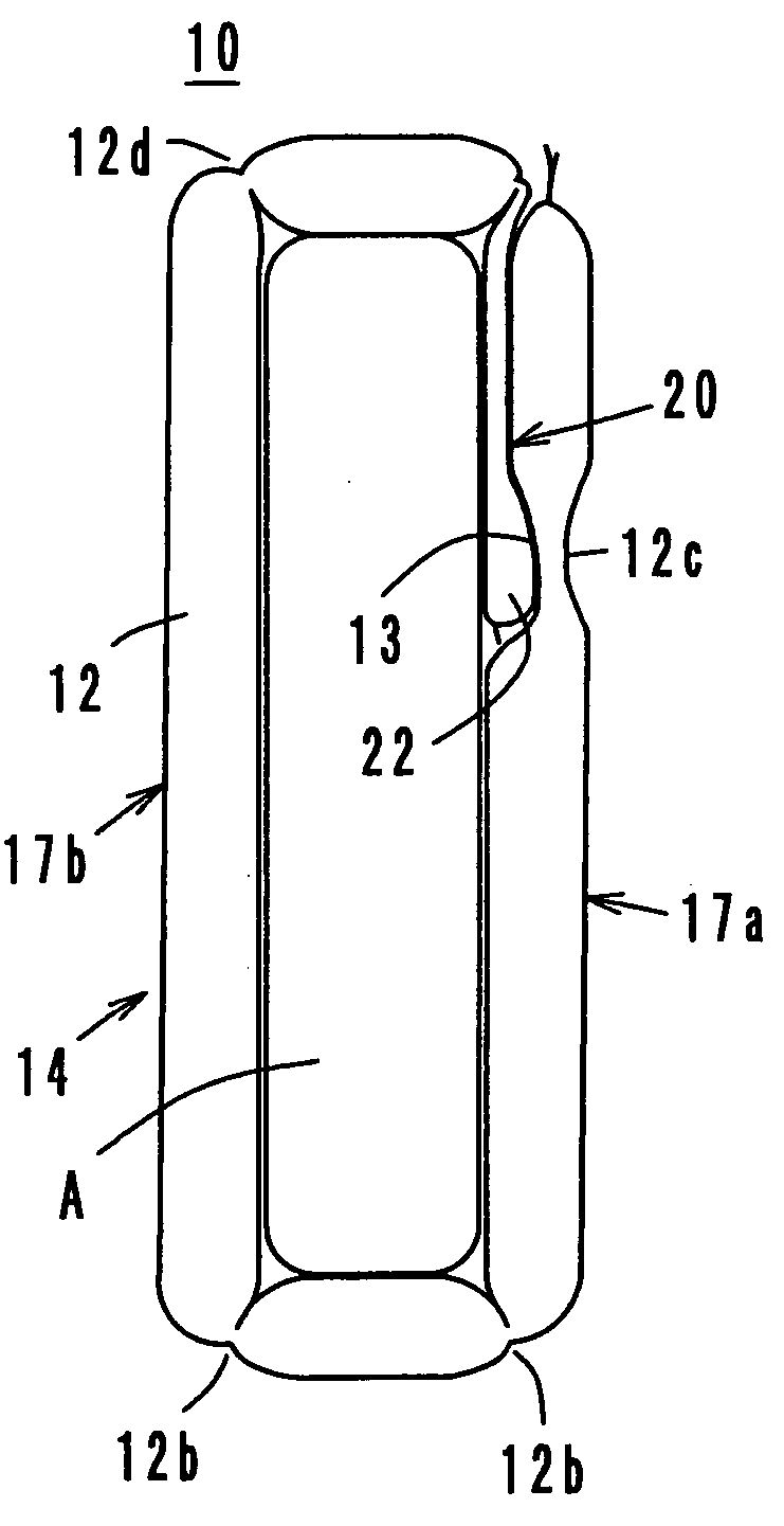
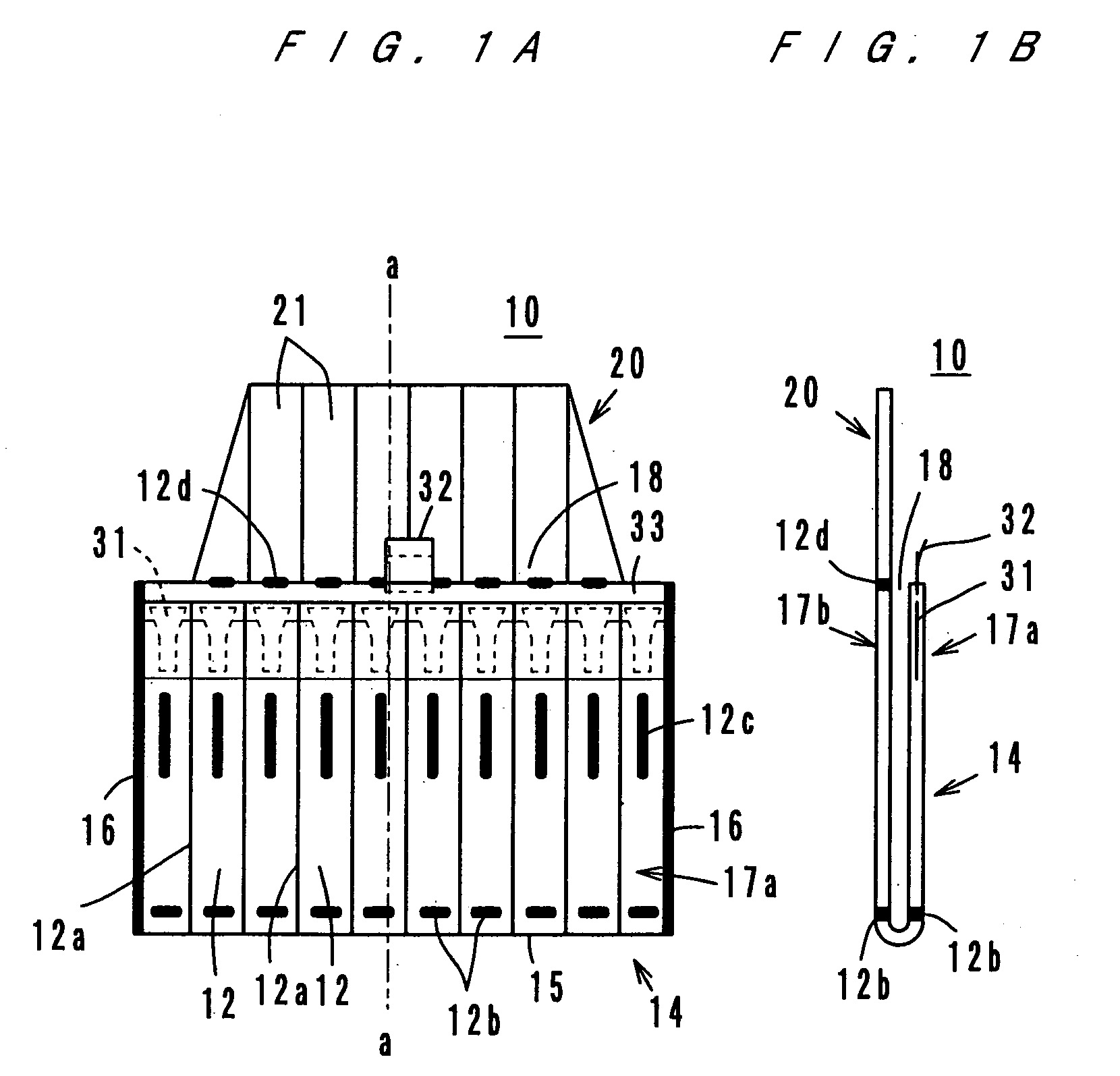
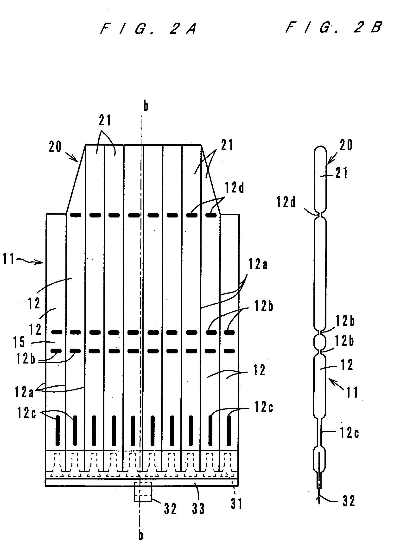
[0028]FIG. 1A is a plan view of a plastic film bag 10 according to a first embodiment of the present invention, and FIG. 2A is a developed view of the plastic film bag 10. The bag 10, as FIG. 2A shows, is made of a plastic tubular material 11 composed of a front film and a back film. By forming fused portions 12a in the tubular material 11 such that the fused portions 12a extend in the direction of the longer side of the bag 10, ten long cells 12 which are arranged in parallel in the direction of the shorter side of the bag 10 are formed. In each of the cells 12, the front film and the back film are fused together at portions 12b and 12c. FIG. 2B shows a state where the respective cells 12 are filled and swollen with air.

[0029] The tubular material 11 is folded substantially in the middle of the longer dimensions of the cells 12, and as FIGS. 1A and 1B show, the folded portions are fused together at both sides 16. Thus, a bag body 14 comprising a front side 17a, a ba...

second embodiment

; See FIGS. 6 through 8

[0043] A plastic film bag according to the second embodiment is basically of the same structure as the plastic film bag according to the first embodiment. In FIGS. 6A and 6B through 8, the same members and parts are provided with the same reference numerals as those in FIGS. 1A and 1B through 3. In the following description of the second embodiment, the point which is different from the first embodiment is described. FIG. 7B is a developed view of the bag body 14 of the plastic film bag according to the second embodiment in a state where the cells 12 and 21 are filled with air.

[0044] The feature of the second embodiment which is different from the first embodiment is that the air injection means comprises a check valve 35 which is provided on an end (the open end 18 of the front side 17a) of the bag body 14 and an air passage 36 which supplies air from the check valve 35 to the cells 12. The check valve 35 is of a well-known type which is used for air injecti...

third embodiment

; See FIGS. 9 through 11

[0046] A plastic film bag according to the third embodiment is basically of the same structure as the plastic film bag according to the first embodiment, and like the plastic film bag according to the second embodiment, this plastic film bag according to the third embodiment has one check valve 35. In FIGS. 9A and 9B through 11A and 11B, the same members and parts are provided with the same reference numerals as those in FIGS. 1A and 1B through 3 and FIGS. 6A and 6B through 8. In the following description of the third embodiment, only the points which are different from the first and second embodiments are described. FIG. 9B is a sectional view of the bag body 14 of the plastic film bag according to the third embodiment in a state where the cells 12 and 21 are filled with air.

[0047] The plastic film bag according to the third embodiment is used to contain a thin item B as shown in FIG. 11A or to contain a small item B′ as shown in FIG. 11B. The features of t...


PUM


Abstract

A plastic film bag with an air cushion has a bag body (14) composed of a front side (17a) and a back side (17b) made by folding a tubular material (11) which has a plurality of plastic film long cells (12) which are arranged and connected in parallel at substantially a center with respect to a direction of longer dimensions of the cells (12) and by fusing the folded portion at both sides (16), a flap (20) which is extended from an open end (18) of the back side of the bag body and which comprises a plurality of cells (21) which communicate with the cells (12) formed in the bag body, and air injection means (31, 32, 33) which is provided for the bag body to inject air into the cells (12, 21). When the cells are filled with air after an item (A) is contained in the bag body, the flap is pressed between the item contained in the bag body and the front side swollen with air, and the flap does not come out easily.

Description

TECHNICAL FIELD [0001] The present invention relates to a plastic film bag, and more particularly to a plastic film bag with an air cushion formed of cells filled with air. BACKGROUND ART [0002] Conventionally, electric appliances like personal computers have been packed with styrene foam used as a cushioning material, and there has been a problem that after unpacking, the cushioning material is left as a large volume of refuse. In order to solve this problem, the Japanese patent laid-open publication No. 9-124073 suggested a plastic film bag with a cushioning formed of a plurality of long cells. After putting an item in the bag, air is injected into the cells, so that the cells filled with air serves as a cushion. A flap with a pressure sensitive adhesive double coated tape thereon is extended from the opening of the bag, and the bag is sealed by folding back the flap and by bonding the flap to the surface of the bag via the adhesive double coated tape. [0003] Thus, the pressure se...

Claims


Application Information

Patent Timeline
IPC IPC(8): B65D30/10B65D81/03B65D81/05B65D81/07
CPCB65D81/052B65D81/03B65D31/16B65D81/07
Inventor ISHIZAKI, AKIRA
Owner ISHIZAKI SHIZAI
Why Eureka
Try Eureka