Process for removing interstitial water from a wastewater sludge

a wastewater sludge and interstitial water technology, applied in the field of wastewater treatment, can solve the problems of large amount of water retained in the interstitial, difficult dewatering of many kinds of sludge, and high cost of flocculation agents, and achieve the effect of reducing the ph of the sludg

Inactive Publication Date: 2005-05-26
SHEPHERD SAMUEL L +1
View PDF11 Cites 11 Cited by
  • Summary
  • Abstract
  • Description
  • Claims
  • Application Information

AI Technical Summary

Benefits of technology

[0025] In the present invention, the carbon dioxide gas is injected at no less than 14.7 p.s.i.a. of pressure. In the preferred embodiment of the present invention, the chamber is a pipeline. The sludge is introduced into one end of the pipeline. The carbon dioxide gas is injected into the sludge adjacent one end of the pipeline. The pipeline will have a length suitable for allowing the carbon dioxide gas to reach equilibrium saturation within the sludge.
[0026] In

Problems solved by technology

Many kinds of sludges are difficult to dewater with conventional dewatering equipment such as chamber filter presses, belt filter presses and other similar equipment.
Unfortunately, the use of such flocculation agents is a rather expensive process and, as such, it is considered desirable to use flocculants very sparingly.
One of the major problems associated with prior attempts to dewate

Method used


Image

  • Process for removing interstitial water from a wastewater sludge
  • Process for removing interstitial water from a wastewater sludge

Examples


Embodiment Construction

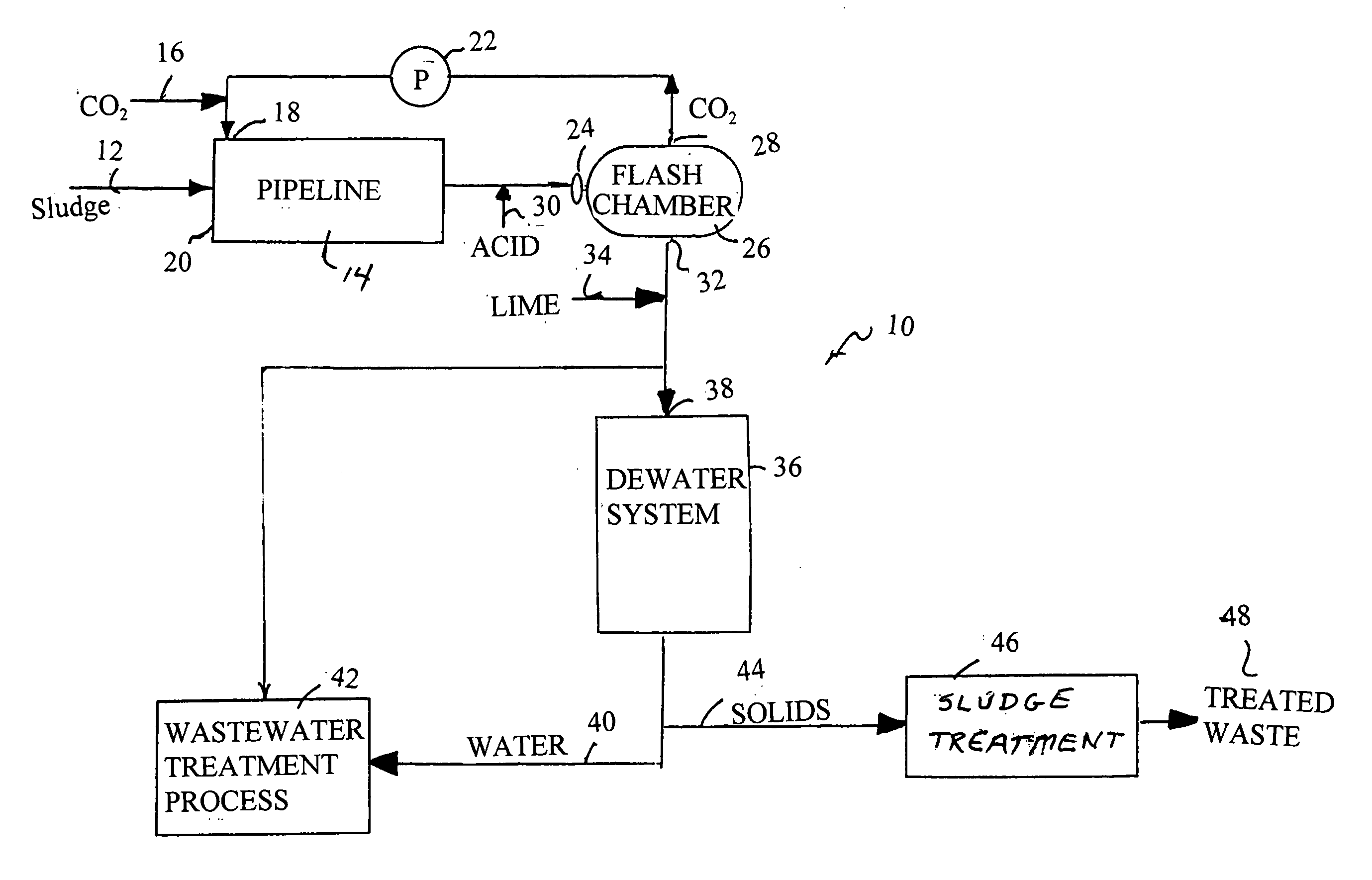
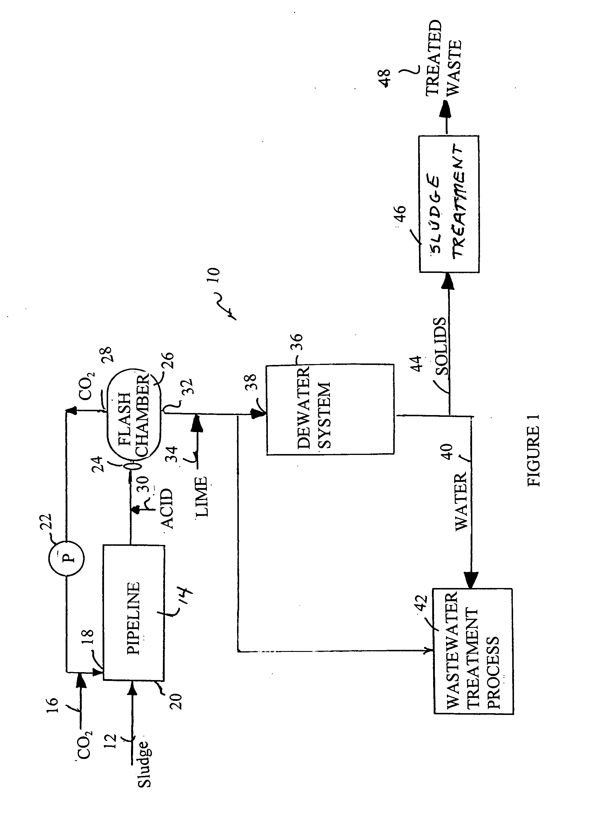
[0030] Referring to FIG. 1 there is shown the process 10 of the present invention for the dewatering of sludge prior to passing to wastewater treatment processes. Initially, in FIG. 1, it can be seen that the sludge 12 is illustrated as passing to a chamber, such as pipeline 14. The sludge 12 is a wastewater sludge having a relatively high water content. The pipeline 14 can be suitably closed so as to allow pressure elevations therein. The pipeline 14 will have suitable length so as to allow the sludge a proper residence time therein under the pressure of carbon dioxide gas 16 introduced through inlet 18 of the pipeline 14.

[0031] When the process 10 of the present invention is a continuous process, the carbon dioxide gas 16 will be injected through inlet 18 into the pipeline 14 adjacent one end 20 of the pipeline 14. As such, the carbon dioxide gas 16 is mixed with the sludge 12 immediately upon entrance into the pipeline. Within the concept of the present invention, it is importan...


PUM

PropertyMeasurementUnit
Pressureaaaaaaaaaa
Diameteraaaaaaaaaa
Lengthaaaaaaaaaa

Abstract

A process for removing water from sludge has the steps of passing the sludge through a chamber, injecting carbon dioxide gas under pressure into the chamber as the sludge passes through the chamber, and flashing the carbon dioxide-injected sludge through an orifice into a vessel so as to release carbon dioxide gas from the sludge. The flashed sludge is returned to a digester or is dewatered to remove water from the sludge. The carbon dioxide gas is injected at no less than 14.7 p.s.i.a. of pressure.

Description

RELATED U.S. APPLICATIONS [0001] The present application is a continuation-in-part of U.S. application Ser. No. 10 / 228,382, filed on Aug. 27, 2002 and entitled “Process for Removing Interstitial Water From a Wastewater Sludge”, presently pending.STATEMENT REGARDING FEDERALLY SPONSORED RESEARCH OR DEVELOPMENT [0002] Not applicable. REFERENCE TO MICROFICHE APPENDIX [0003] Not applicable. FIELD OF THE INVENTION [0004] The present invention relates to wastewater treatment. More particularly, the present invention relates to anaerobic and aerobic digestion processes that are enhanced through microorganism cell lysis, sludge particle reduction and increases in available soluble organic matter. Furthermore, the present invention relates to processes for removing interstitial water from cellular material during wastewater treatment processes. BACKGROUND OF THE INVENTION [0005] Sewage is composed of the liquid and water-carried wastes from residences, commercial buildings, industrial plants,...

Claims


Application Information

Patent Timeline
IPC IPC(8): C02F1/20C02F1/66C02F9/00C02F11/12C02F11/145
CPCC02F1/20C02F1/66C02F9/00C02F11/12C02F11/14C02F2301/063C02F11/145
Inventor SHEPHERD, SAMUEL L.AUSTIN, ARTHUR
Owner SHEPHERD SAMUEL L
Why Eureka
Try Eureka