End point detector for etching equipment

a technology of etching equipment and end point detection, which is applied in the manufacture of cables/conductor parts, instruments, optical elements, etc., can solve the problems of end point detection errors and scratches on the surface of viewing windows, and achieve the effect of reducing or eliminating damag

Inactive Publication Date: 2005-05-26
SAMSUNG ELECTRONICS CO LTD
View PDF5 Cites 6 Cited by
  • Summary
  • Abstract
  • Description
  • Claims
  • Application Information

AI Technical Summary

Benefits of technology

[0014] It would therefore be desirable to provide an arrangement that can reduce or eliminate damage, such as scratches, on the surface of a viewing window during removal and replacement of a connector from / into a bracket of the viewing window.

Problems solved by technology

The impurities on viewing window 5 deteriorate light transmittance and may cause errors in the end point detection.
However, continual removal and replacement of connector 7 from / into bracket 5a leave scratches on the surface of viewing window 5.

Method used


Image

  • End point detector for etching equipment
  • End point detector for etching equipment
  • End point detector for etching equipment

Examples


Embodiment Construction

[0022] Now, the present invention will be described in detail by way of an embodiment with reference to the accompanying drawings.

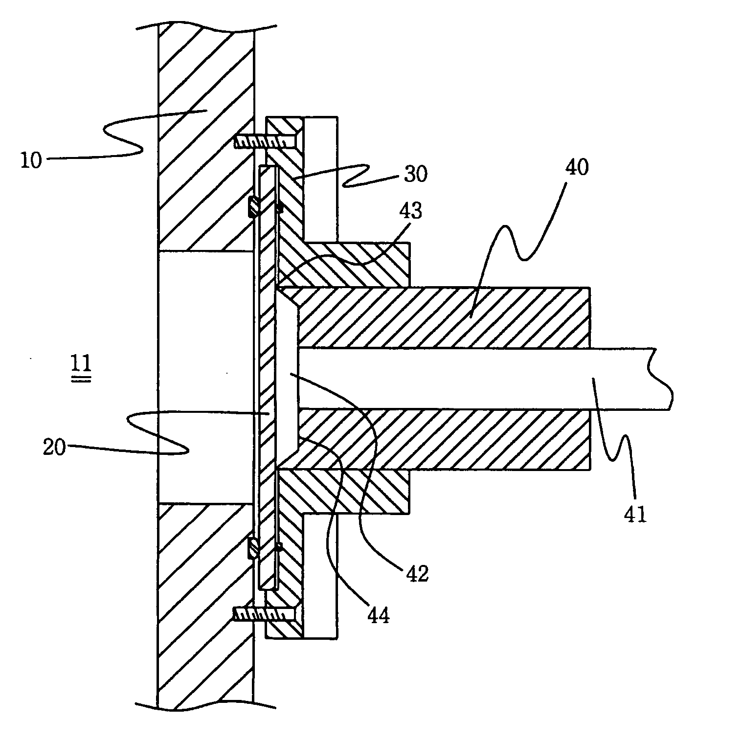
[0023]FIG. 3 shows a portion of a process chamber 11 including a chamber wall 10 having an opening formed therein, a viewing window 20 disposed over the opening in the chamber wall 10, a bracket 30 connected to the chamber wall 10 around a periphery of the viewing window 20, a connector 40 engaged within the bracket 30 having a first end 43 in contact with the viewing window 20, and an optical cable 41 disposed within the connector 40 having a first end adapted to receive light from the inside of process chamber 11 by means of the viewing window 20.

[0024] Advantageously, the first end 43 of connector 40 is recessed to a predetermined depth to form a recess 42, minimizing the contact area between connector 40 and a viewing window 20.

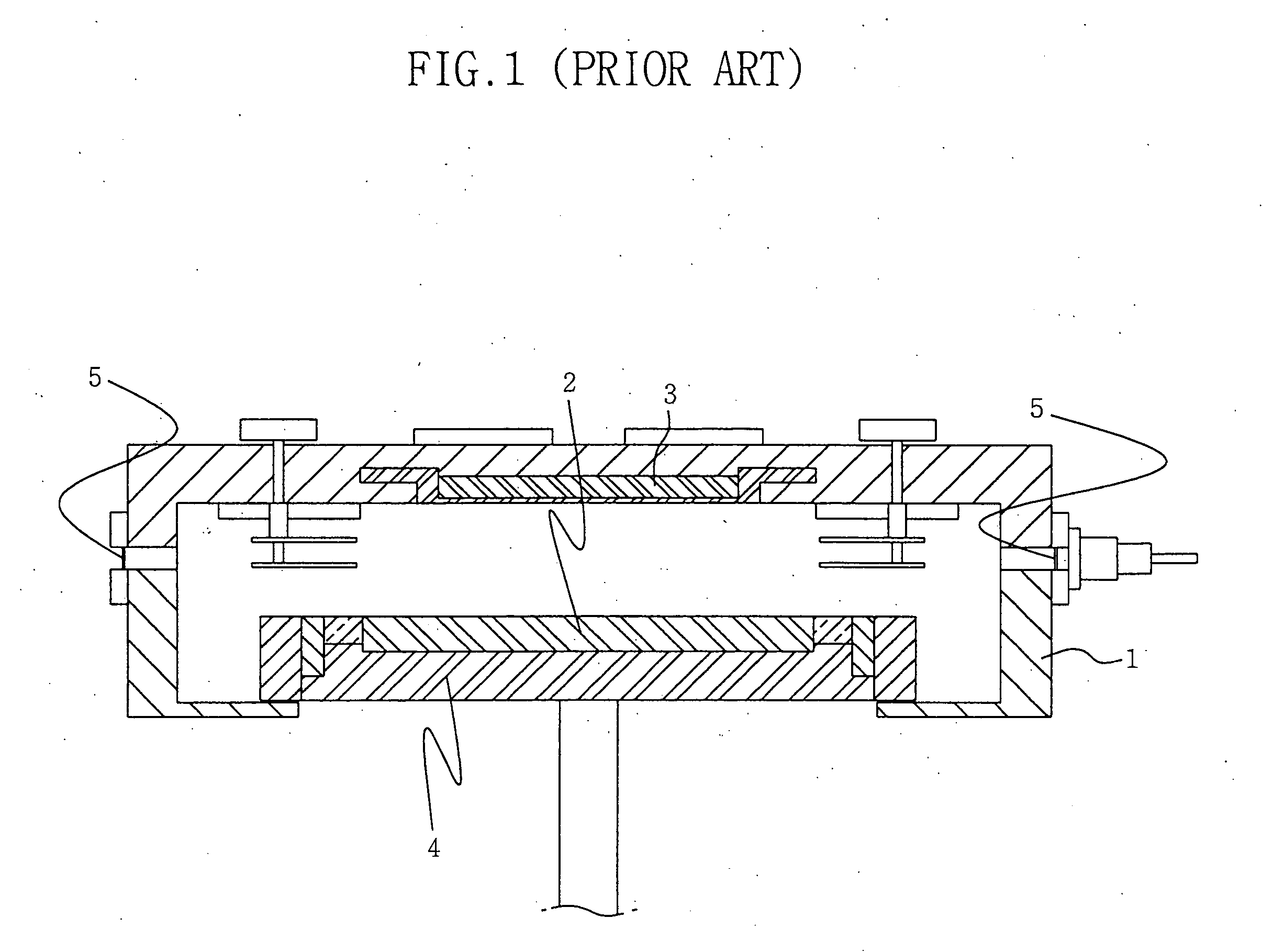
[0025] Beneficially, process chamber 11 includes an electrostatic chuck (see FIG. 1) to hold a wafer, and electrodes for g...


PUM

PropertyMeasurementUnit
surface areaaaaaaaaaaa
shapeaaaaaaaaaa
semiconductoraaaaaaaaaa

Abstract

The present invention relates to an end point detector for etching equipment. The embodiment of the present invention has a unique feature which allows for a minimal contact between a connector and viewing window. This feature prevents scratches on the surface of the viewing window when the connector is removed or replaced.

Description

CROSS REFERENCES TO RELATED APPLICATIONS [0001] This application claims the priority of Korean Patent Application No. 2003-75748, filed on 29 Oct. 2003, the contents of which are hereby incorporated by reference in their entirety as if fully set forth herein. BACKGROUND OF THE INVENTION [0002] The present invention relates to an end point detector used in etching equipment. More particularly, the present invention relates to an end point detector that minimizes a contact area between a viewing port and an optical cable-fixing connector, which reduces scratches and wear and tear on the surface of a viewing window during removal and replacement of connector. [0003] An end point detector (EPD) is an apparatus applied to a process chamber, specifically an etching chamber, used for a semiconductor device fabrication process. [0004] More specifically, a window is installed over an opening in a wall of an etching chamber, and light emitted or received through the window is transmitted to d...

Claims


Application Information

Patent Timeline
Patent Type & Authority Applications(United States)
IPC IPC(8): H01L21/3065G02B6/38H01J37/32H01L21/00
CPCG02B6/3847G02B6/3897H01L21/67253H01J37/32935H01J37/32963H01J37/32871H01L21/3065
Inventor OH, SANG-DO
Owner SAMSUNG ELECTRONICS CO LTD
Why Eureka
Try Eureka