Centering mandrel for turning wheels

a technology of turning wheel and centering shaft, which is applied in the field of hand tools, can solve the problems of inability to accurately position the non-centering shaft, the difficulty of providing centered wheels by children, and the out of round wheels, etc., and achieves low manufacturing cost and low price. , the effect of easy and efficient manufacturing and marketing

Inactive Publication Date: 2005-05-26
LAUNIUS WILLIAM E JR
View PDF35 Cites 10 Cited by
  • Summary
  • Abstract
  • Description
  • Claims
  • Application Information

AI Technical Summary

Benefits of technology

[0015] It is another object of the present invention to provide a new and improved centering mandrel that may be easily and efficiently manufactured and marketed.
[0016] An even further object of the present invention is to provide a new and improved centering mandrel that has a low cost of manufacture with regard to both materials and labor, and which accordingly then has low prices enticing to the consuming public, thereby making such a centering mandrel economically available to children and their sponsors.

Problems solved by technology

The difficulty in providing centered wheels by children is shown by the operation of a typical device.
Differences in diameter between the threaded

Method used


Image

  • Centering mandrel for turning wheels
  • Centering mandrel for turning wheels
  • Centering mandrel for turning wheels

Examples


Embodiment Construction

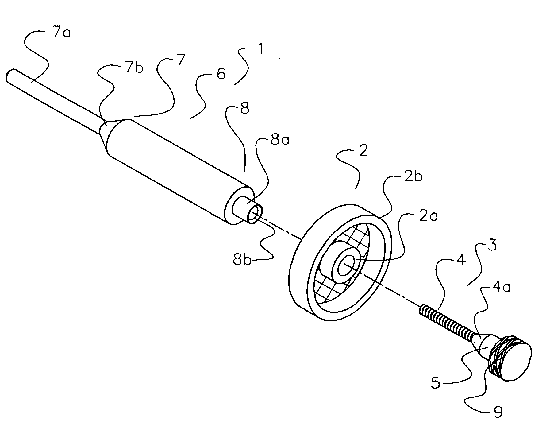
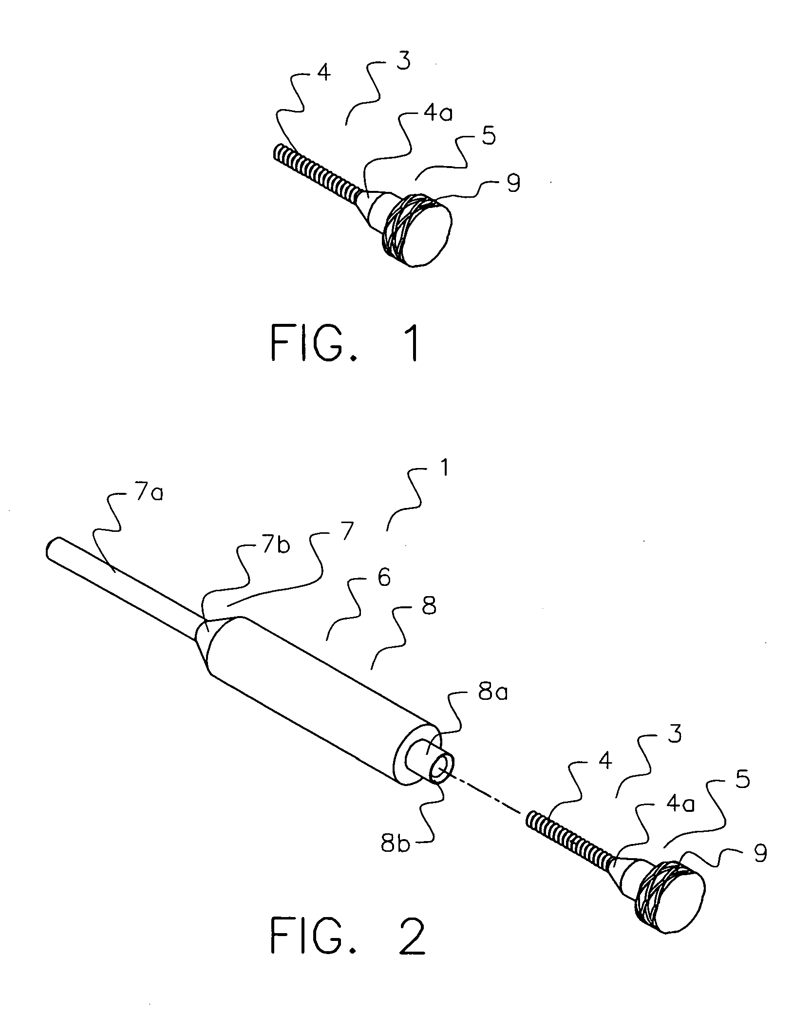
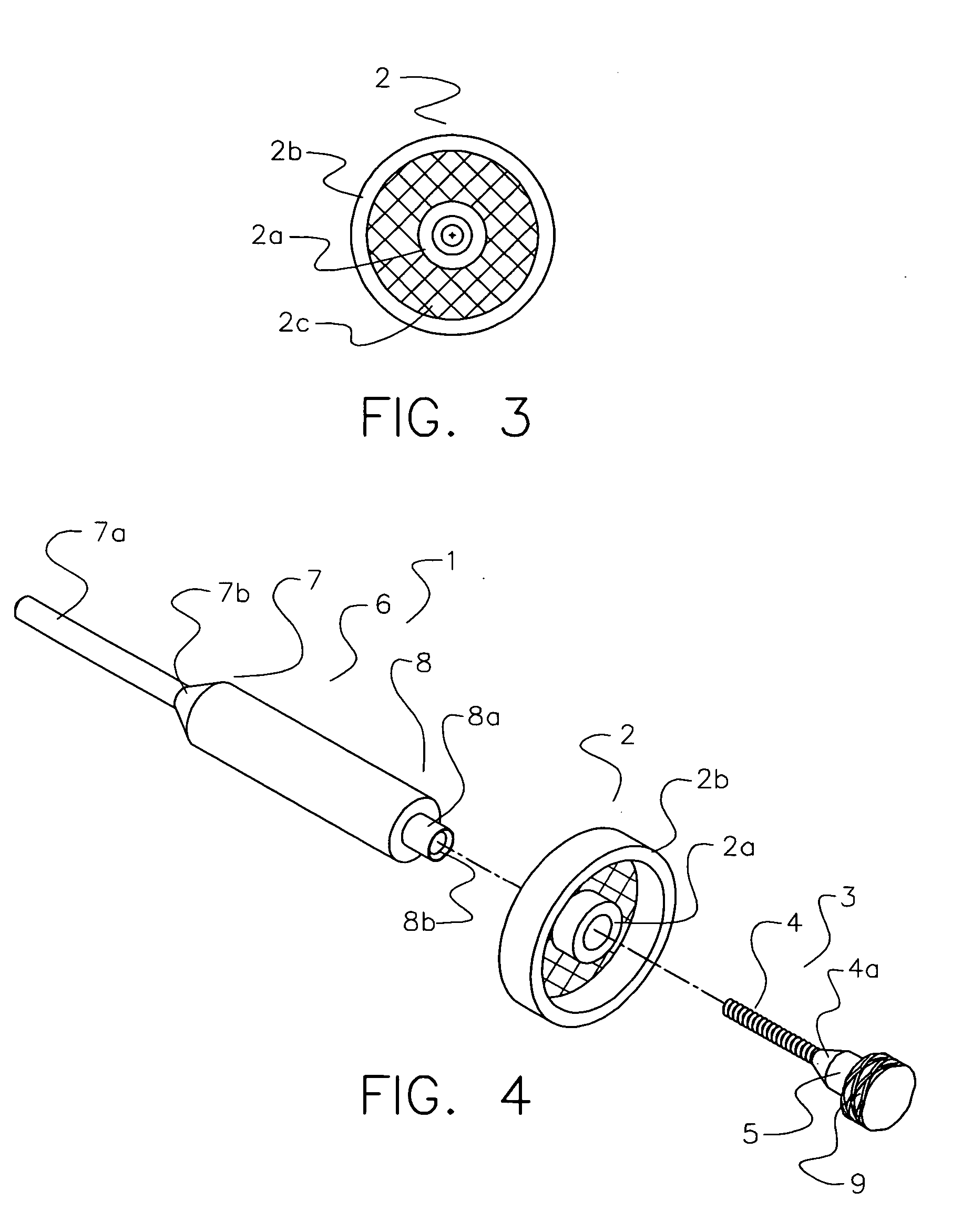
[0025] The present invention overcomes the prior art limitations by centering a wheel and accepting a reverse mount of the wheel. In FIG. 1, the centering mandrel 1 begins with a threaded rod 3, generally cylindrical in shape, with a free or first end 4 and an opposite second end 5. The second end 5 joins the apex of a truncated cone 4a. The base of the cone 4a has a wider diameter than the threaded rod 3 but less than the diameter of a hub of a wheel 2. The base of the cone 4a then attaches to a cylindrical knob 9. The knob 9 is knurled to ease manual turning and has a diameter greater than the hub in the preferred embodiment.

[0026] In addition to the rod 3, the centering mandrel 1 has a body 6 shown in FIG. 2. The body 6 has a generally round cylindrical shape, a first end 7, and an opposite second end 8. The first end 7 has a conical portion 7b of the body 6 extending into a cylindrical shaft 7a of a diameter less than that of the body 6. The shaft 7a has sufficient length for a...


PUM


Abstract

The present invention centers a hub of a wheel upon a mandrel so the wheel rotates about an axis precisely perpendicular to the plane of the wheel. The centering mandrel has a body, and a rod secured to the body. The cylindrical body has a shaft for connection to a rotating chuck. Opposite the shaft, the body receives the rod in a threaded cylinder. The cylindrical rod has threads to engage the cylinder and has a knob for manual turning. In operation, a child places a wheel upon the cylinder, inserts the rod through the hub, and turns the knob to secure the wheel. Then a parent places the shaft into a chuck for turning the wheel and truing using hand tools.

Description

CROSS REFERENCE TO RELATED APPLICATION [0001] This non-provisional patent application claims priority to the provisional application for patent having Ser. No. 60 / 524,658 and filed on Nov. 25, 2003.BACKGROUND OF THE INVENTION [0002] This invention relates to hand tools in general and more specifically to a tool that centers wheels on mandrels for finishing. As winter loosens its grip, children emerge from homes across the land for contests such as the “Pinewood Derby.”[0003] For the derby, children and their adult sponsors assemble a wooden car from a kit and then race their cars against those of fellow children upon a track. Children that win local races advance to tournaments. As a car race, speed remains essential to victory. Children and sponsors seek to minimize wheel friction and align wheels precisely to the track at each opportunity. [0004] The wooden cars have four wheels: plastic with a finished face, a rim, and a centered hub opposite the finished face. The finished face ...

Claims


Application Information

Patent Timeline
IPC IPC(8): B23B31/00B23B31/40
CPCY10T279/16B23B31/40
Inventor LAUNIUS, WILLIAM E. JR.
Owner LAUNIUS WILLIAM E JR
Why Eureka
Try Eureka