System and method for acquiring voltages and measuring voltage into an electrical service using a non-active current transformer

Inactive Publication Date: 2005-05-26
ITRON
View PDF6 Cites 29 Cited by
  • Summary
  • Abstract
  • Description
  • Claims
  • Application Information

AI Technical Summary

Benefits of technology

[0008] It is another object of the present technology to provide a system and method for accurately measuring the input voltage of an electrical service over a relatively wide input voltage range. Since typical exemplary metering voltages include 120, 240, 277 and 480 volts, functional operation over a range inclusive of 96-576 volts may be preferred in some embodiments. Subsets of this dynamic range or larger inclusive ranges may be preferred in other embodiments.
[0009] It is a still further object of the present subject matter to use current transformers in circuitry for measuring input voltage, wherein such current transformers are configured in a non-active fashion requiring only first and second windings. A smaller, more cost-effective solution is effected by eliminating the need for a third winding to regulate undesired flux levels in the current transformers. To overcome the need for a third winding, core materials for the current transformers are chosen with predictable magnetic properties as a function of increased flux levels. Predictable operation of the current transformer facilitates accurate compensation of any phase shift in the voltage acquisition circuitry.
[0010] These objects as well as

Problems solved by technology

Both such known exemplary voltage acquisition circuitry configurations may also be relatively large and expensive, thus making them impractical for some electric utility meter embodiments.
While various aspects and alternative embodiments may be know

Method used


Image

  • System and method for acquiring voltages and measuring voltage into an electrical service using a non-active current transformer
  • System and method for acquiring voltages and measuring voltage into an electrical service using a non-active current transformer
  • System and method for acquiring voltages and measuring voltage into an electrical service using a non-active current transformer

Examples


embodiment 40

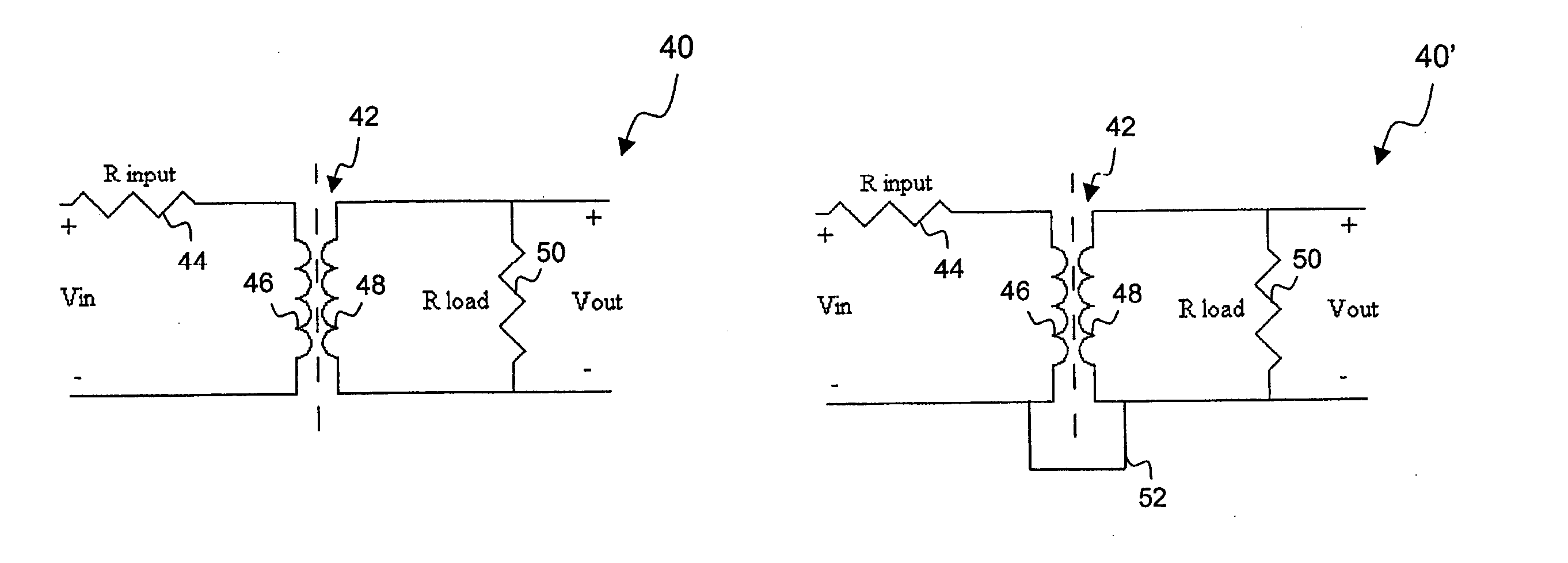
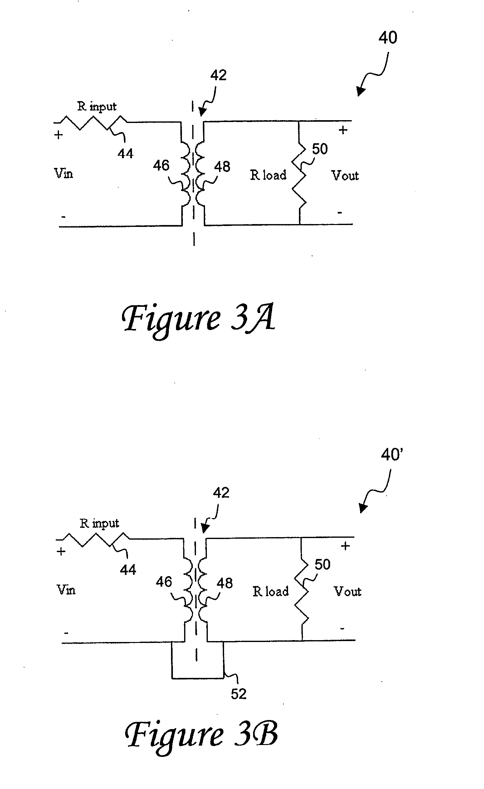
[0039] The present disclosed voltage acquisition circuitry provides an ability to provide circuit isolation, such as effected in the exemplary circuit embodiment 40 of FIG. 3A. However, other embodiments of the presently disclosed non-active current transformer technology may not provide isolation. Such is the case when the respective negative terminals defining the input and output voltage in circuit 40′ of FIG. 3B are connected together by lead 52. It should be appreciated that both such exemplary configurations are appreciated in accordance with the present subject matter.

[0040] Current transformer 42 is unique in that it does not require a third feedback winding. The material of the core in current transformer 42 preferably corresponds to a high permeability material with predictable magnetic properties as a function of increased flux levels in the transformer. Examples of such a core material correspond to crystalline NiFe, nanocrystalline and amorphous cores, particular exampl...

embodiment 60

[0043] Voltage acquisition circuits in accordance with the presently disclosed technology, examples of which have been presented in FIGS. 3A and 3B, may be utilized to measure the voltage on each phase of an electrical service. An example of how exemplary voltage acquisition circuit 40 or 40′ may be incorporated into a meter embodiment 60 is illustrated in FIG. 4. Exemplary components of a meter 60 are depicted in a three-phase electrical service environment, but it should be appreciated that the subject voltage acquisition circuitry may also be employed in single-phase or other polyphase environments in a similar fashion.

[0044] Referring more particularly to FIG. 4, a three-phase electrical service yields voltage and current signals at three phases (A, B and C). The three input voltage signals are referred to as VA, VB and VC, while the three input current signals are referred to as IA, IB and IC. Respective voltage acquisition circuits 40a, 40b and 40c respectively receive input v...


PUM


Abstract

A voltage acquisition circuit for sensing input voltage signals in each phase of an electrical service includes a non-active current transformer configuration that is operable over a wide input voltage range. The current transformer configuration includes primary and secondary windings, an input resistor and a burden resistor across which an output voltage is defined. The input resistor may be relatively large, such as on the order of about one MΩ and the transformer core may have a nanocrystalline core characterized by predictable magnetic properties versus varied transformer flux levels. This operational predictability facilitates phase compensation via digital filtering or otherwise for any phase shift induced between input and output voltages of the current transformer. The subject voltage acquisition circuits may be provided to sense each phase of a single-phase or polyphase electrical service, whereby the sensed voltages are subsequently provided to additional components of an electricity meter, such as a power supply or other processing components, including an A/D converter and microprocessor for determining energy quantities.

Description

CROSS REFERENCE TO RELATED APPLICATIONS [0001] This application claims priority under 35 USC 119(e) of Provisional Patent Application Ser. No. 60 / 484,065 filed Jul. 1, 2003, entitled “SYSTEM AND METHOD OF MEASURING VOLTAGE INTO AN ELECTRICAL SERVICE USING A NON-ACTIVE CURRENT TRANSFORMER,” which is hereby incorporated by reference in its entirety.BACKGROUND OF THE INVENTION [0002] The present subject matter generally concerns voltage acquisition technology that can be utilized to measure voltage signals into an electrical service (with the present subject matter adapted for either single phase or multi-phase, as determined by a user's needs). More particularly, the subject voltage acquisition technology corresponds to non-active current transformers that provide effective voltage sensing over a wide input voltage range. Different embodiments and aspects of the present subject matter may equally take the form of either apparatus or methodology. [0003] Utility providers employ various...

Claims


Application Information

Patent Timeline
IPC IPC(8): G01RG01R11/32G01R15/18G01R19/25
CPCG01R19/2513G01R15/183B82Y30/00G01R11/32
Inventor MARTIN, BRENT T.MOORE, MICHAEL E.LAKICH, DANIEL M.
Owner ITRON
Why Eureka
Try Eureka