
Non-uniform view weighting tomosynthesis method and apparatus

a tomosynthesis and non-uniform view technology, applied in tomography, instruments, nuclear engineering, etc., can solve the problems of many problems and inconsistencies in the reconstructed imag

Active Publication Date: 2005-05-26
GE MEDICAL SYST GLOBAL TECH CO LLC
View PDF3 Cites 32 Cited by
  • Summary
  • Abstract
  • Description
  • Claims
  • Application Information

AI Technical Summary

Problems solved by technology

This uniform view weighting, however, causes many problems and inconsistencies in the reconstructed images.
These issues may, then, result in artifacts such as wavy patterns in the reconstructed images, general fall off of intensity values near edges of the images, and ghost-like images at elevations above, image plane where the subject cannot have been located (i.e. beyond the physical limits of the subject being imaged).

Method used


Image

  • Non-uniform view weighting tomosynthesis method and apparatus
  • Non-uniform view weighting tomosynthesis method and apparatus
  • Non-uniform view weighting tomosynthesis method and apparatus

Examples


Embodiment Construction

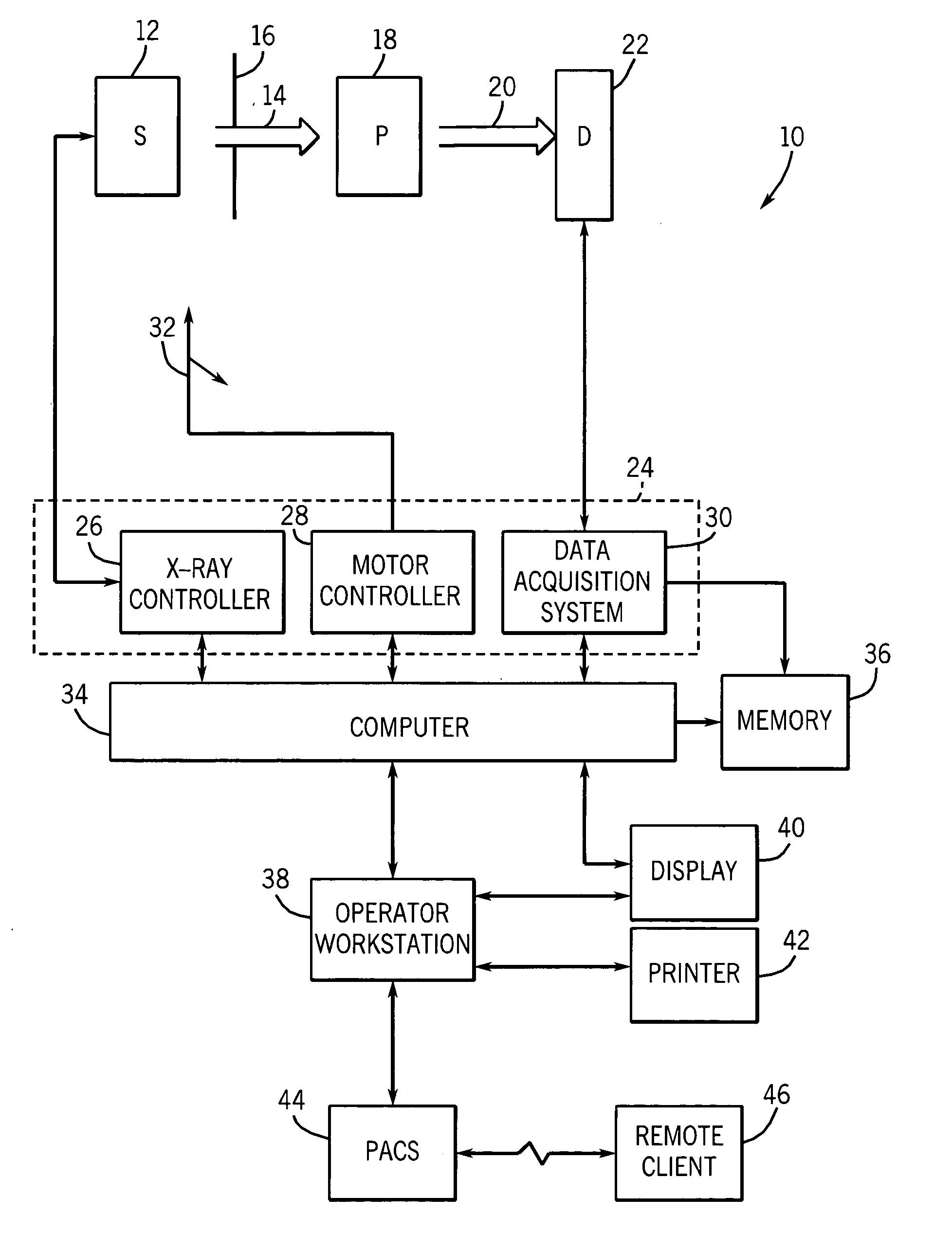
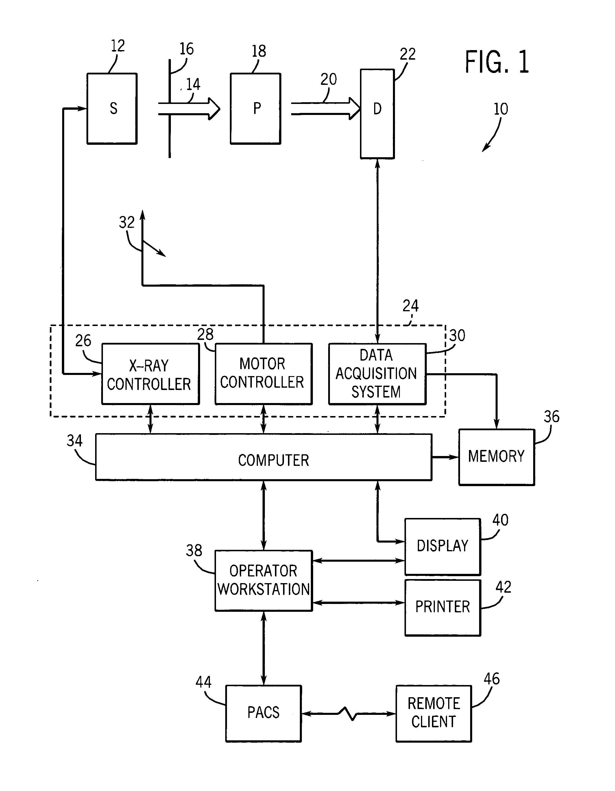
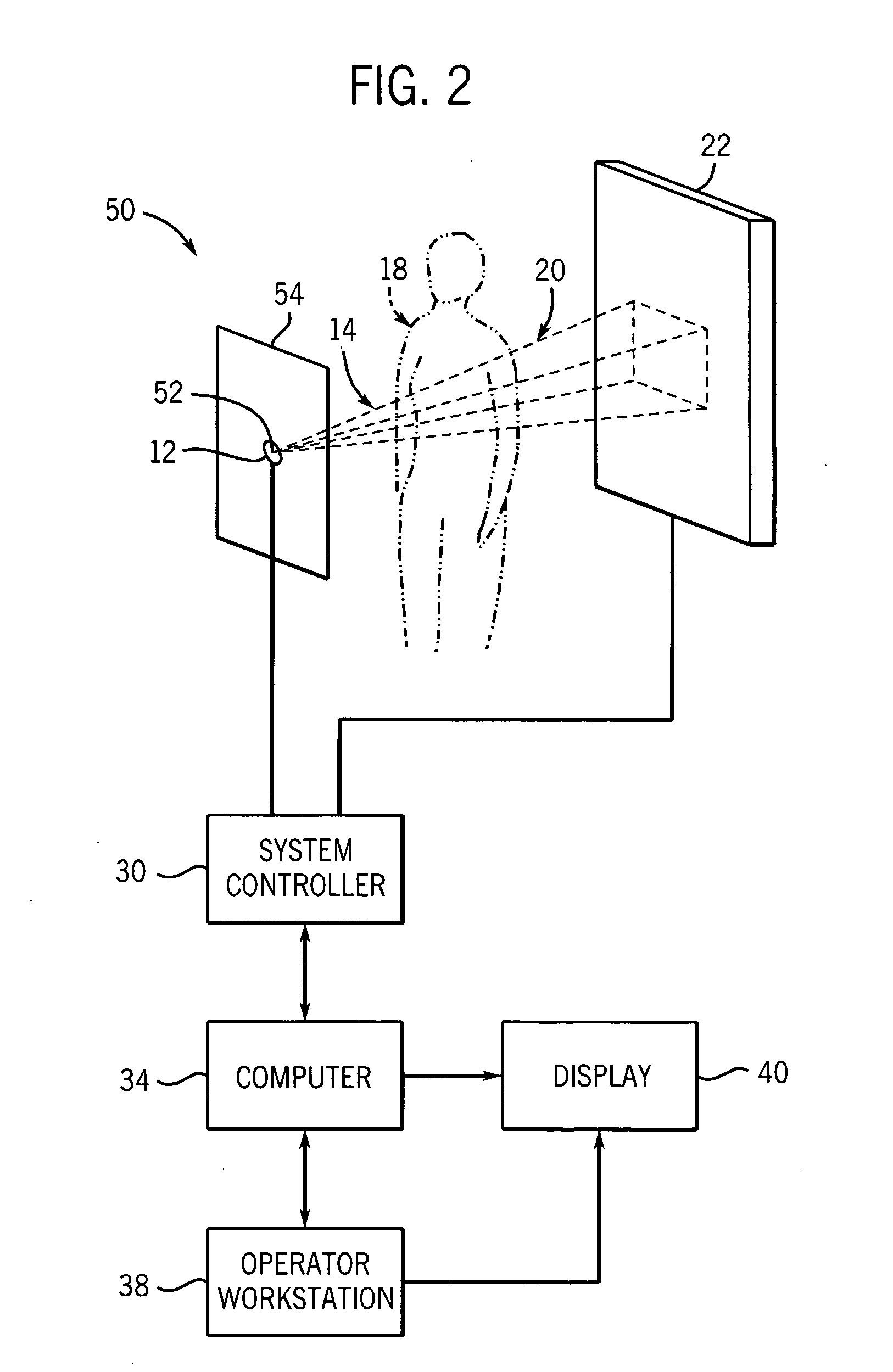
[0014]FIG. 1 is a diagrammatical representation of an exemplary tomosynthesis system, designated generally by the reference numeral 10, for acquiring, processing and displaying tomosynthesis images, including images of various slices through a subject of interest in accordance with the present techniques. In the embodiment illustrated in FIG. 1, tomosynthesis system 10 includes a source 12 of X-ray radiation which is movable generally in a plane, or in three dimensions. In the exemplary embodiment, the X-ray source 12 typically includes an X-ray tube and associated support and filtering components.

[0015] A stream of radiation 14 is emitted by source 12 and passes into a region of a subject, such as a human patient 18. A collimator 16 serves to define the size and shape of the X-ray beam 14 that emerges from the X-ray source toward the subject. A portion of the radiation 20 passes through and around the subject, and impacts a detector array, represented generally by reference numera...


PUM

PropertyMeasurementUnit
electricalaaaaaaaaaa
depthaaaaaaaaaa
heightsaaaaaaaaaa

Abstract

A technique is provided for non-uniform weighting in back-projection calculations in tomosythesis. The non-uniform weighting may include weighting based on a count map of the number of times pixels of individual slices are traversed by radiation in different projections. Weighting may also include non-uniform functions for contributions of features at different slice level to the sensed X-ray attenuation system response inconsistencies are accounted for by further weighting based upon projection maps which may be created in separate system calibration or configuration routines.

Description

BACKGROUND OF THE INVENTION [0001] The present invention relates generally to tomosynthesis imaging systems. More particularly, the invention relates to a technique for correcting or avoiding certain artifacts and generally improving tomosynthesis images by use of non-uniform view weighting. [0002] Tomosynthesis systems have developed over the past decades and now offer significant advantages for many types of imaging, such as in the medical diagnostics field. In general, X-ray tomosynthesis involves the use of low dose X-ray radiation to produce a series of images acquired over a range of X-ray beam orientations relative to an image object. In currently available systems the object is positioned in front of a digital detector and the X-ray source is moved to various positions to produce the series of images. A number of such images may be produced, typically in excess of 50 or 60. The detector collects electrical data representative of the depletion of a charge at individual pixel ...

Claims


Application Information

Patent Timeline
Patent Type & Authority Applications(United States)
IPC IPC(8): A61B6/02A61B6/03G06T11/00
CPCA61B6/025G06T2211/436G06T11/005
Inventor LI, BAOJUNCLAUS, BERNHARD ERICH HERMANNAVINASH, GOPAL B.METZ, STEPHEN W.HSIEH, JIANG
Owner GE MEDICAL SYST GLOBAL TECH CO LLC
Learn More