Air operated unloading device

a technology of air-operated unloading and unloading device, which is applied in the direction of lifting device, turning machine accessories, manufacturing tools, etc., can solve the problems of increasing the danger to the operator, slowing down the production time, and many automated loading and unloading devices are too complex and expensive to justify their use in all but the most elaborate and expensive machine tools. , to achieve the effect of easy discharge, simple or eliminating, and increasing the ra

Active Publication Date: 2005-05-26
J F BERNS
View PDF25 Cites 12 Cited by
  • Summary
  • Abstract
  • Description
  • Claims
  • Application Information

AI Technical Summary

Benefits of technology

[0012] Generally, the present invention provides a device for effecting an unloading operation of a workpiece with respect to a machine tool. The device includes a non-rotating dump tube having one end adapted for communication with a machine tool and a sidewall defining an opening for discharging a workpiece, a vacuum chamber enclosing the opening in the sidewall and including a workpiece outlet, the chamber configured to receive a workpiece from the dump tube, a door selectively sealingly engaged with the workpiece outlet, and configured to allow the unloading of a workpiece, and a source of vacuum coupled to the vacuum chamber and configured to draw a work piece through the dump tube and into the vacuum chamber for unloading. An actuator may be included to operatively engaged and open the door to unload a workpiece. An impact absorber may also be included to absorb the impact of a workpiece as it is drawn into the dump tube. The impact absorber may also aid in locating a workpiece proximate the opening in the sidewall so that the workpiece may be readily discharged. Such an unloading device need not rotate the dump tube to effectuate unloading a workpiece, and, thereby, simplifies or eliminates the need for a rotating mechanism.
[0013] The invention further contemplates a coupling between the unloading device and a machine tool. Such a coupling allows the machine tool to continue to operate or rotate at increased rates during an unloading operation. Allowing a machine tool to continue to rotate at increased rates while unloading workpieces reduces unloading times. Further, allowing a machine tool to continue to rotate at increased rates while unloading workpieces decreases wear on a machine tool motor, increases the motor life, and, generally, decreases the amount of electric power the motor consumes.

Problems solved by technology

The intervention of machine tool operators during the process slows the production time and presents additional dangers to the operator.
Many automated loading and unloading devices are too complex and expensive to justify their use in any but the most elaborate and expensive machine tools.
While needs exist in the industry for these sophisticated and expensive machine tool loading and unloading mechanisms, especially in connection with many high volume machining operations, these solutions to the problems associated with manual loading and unloading operations can be too expensive.
First, unloading times are, in part, based on the time necessary for the machine tool to stop or slow, and waiting for a machine tool to stop or slow generally increases unloading times. Second, constantly stopping or slowing the machine tool increases wear on the motor of the machine tool, thereby reducing motor life, and, third, stopping or slowing the machine tool generally increases the amount of electric power the motor consumes.

Method used


Image

  • Air operated unloading device
  • Air operated unloading device
  • Air operated unloading device

Examples


Embodiment Construction

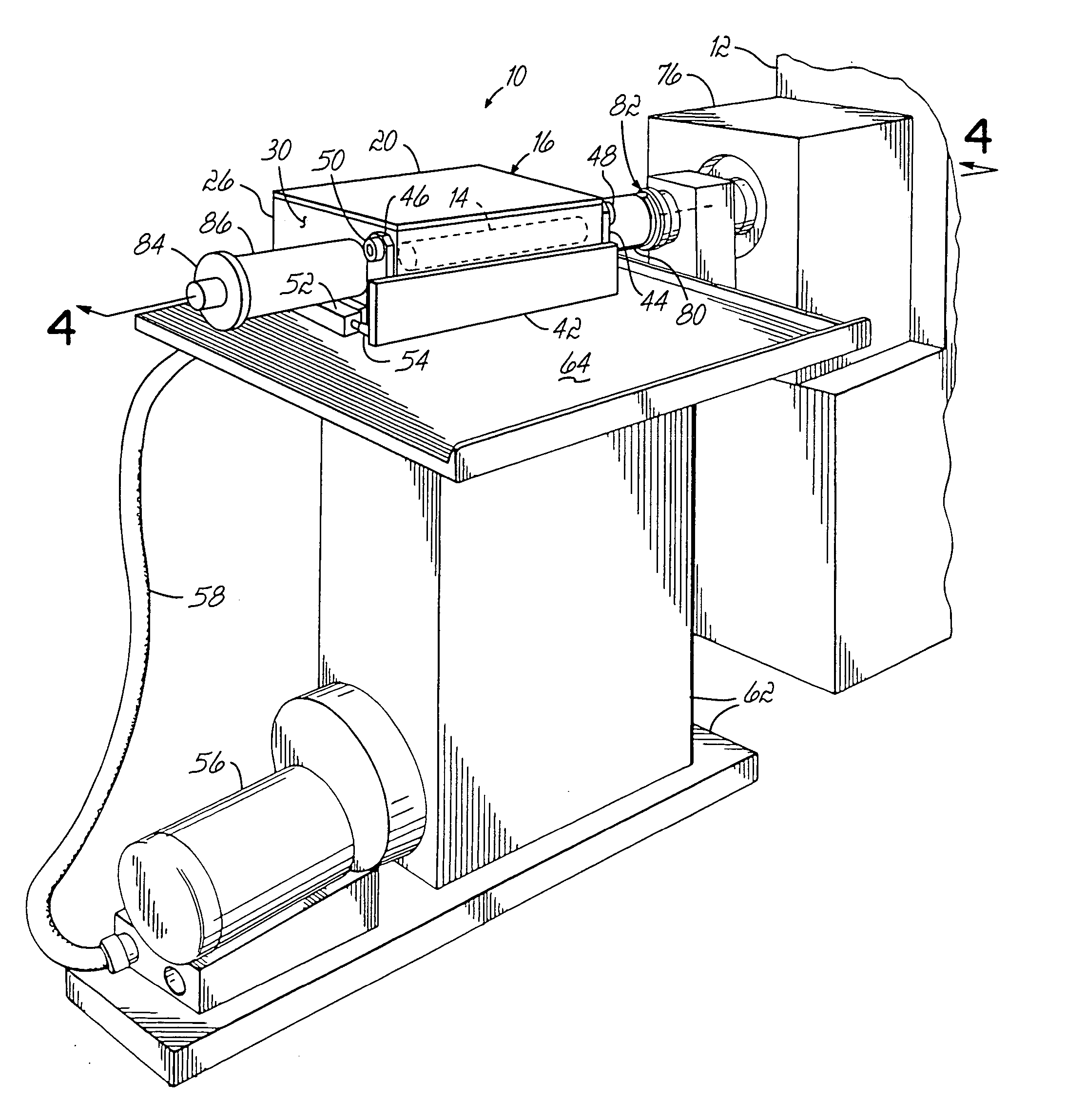
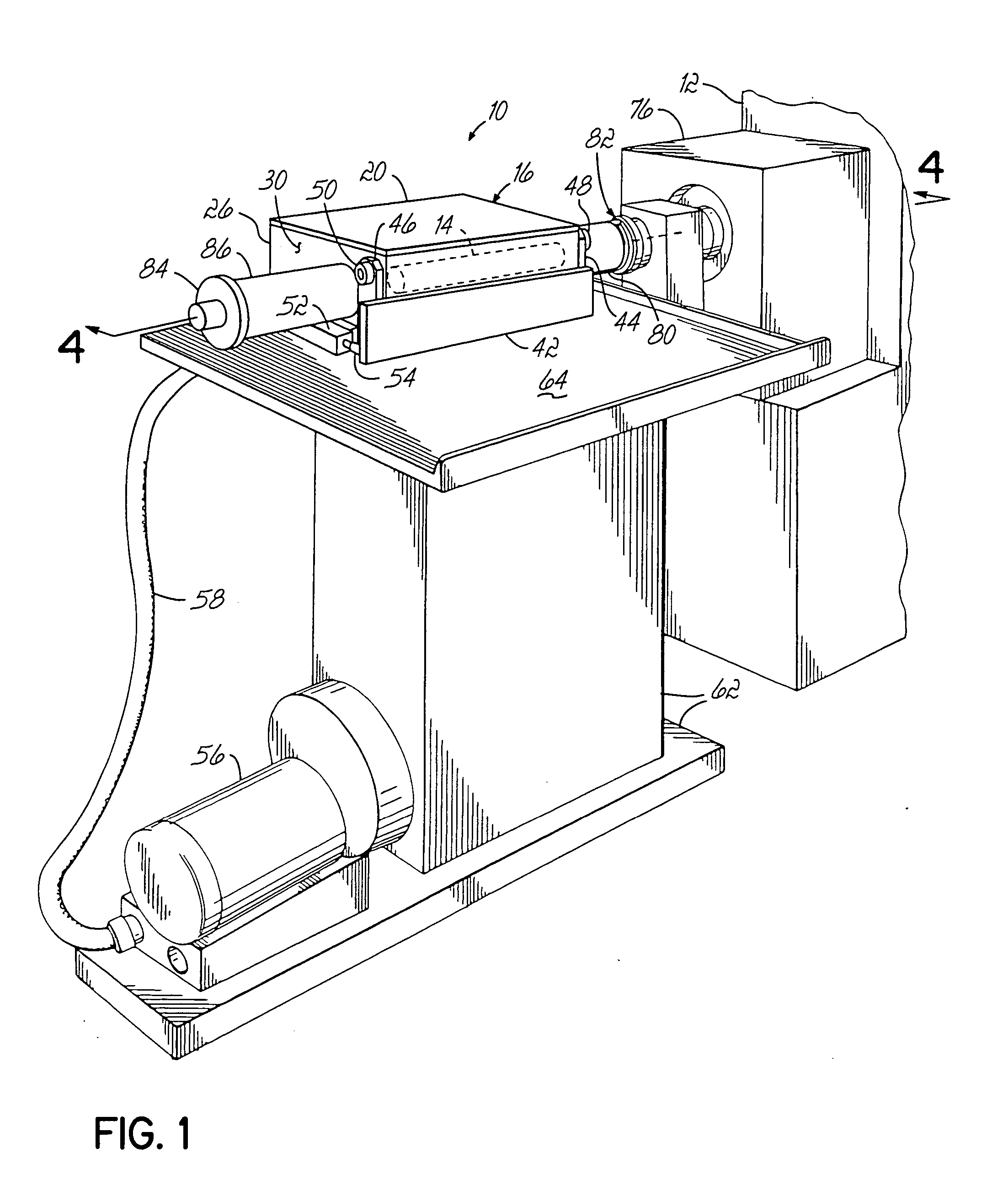
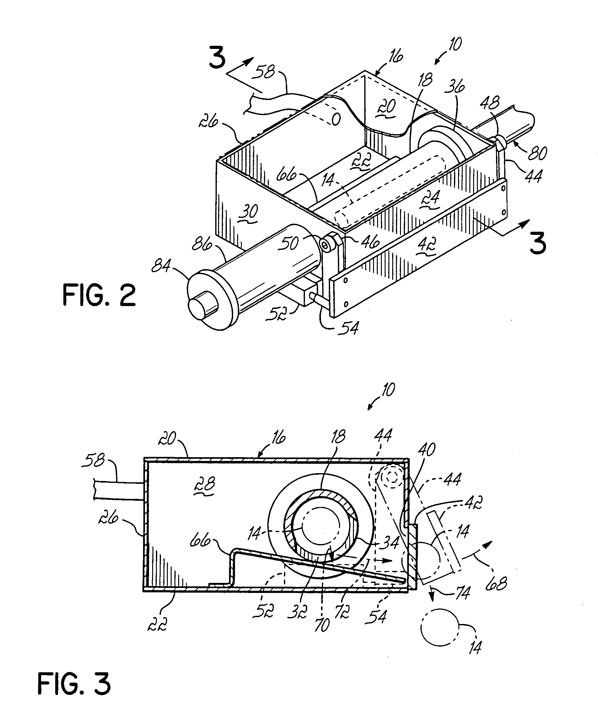
[0023] Referring to FIGS. 1-4, an unloading device 10 constructed in accordance with a first embodiment of the invention is shown coupled to a lathe 12. Device 10 is used only as an unloading device and operates to retrieve workpieces 14 from lathe 12 into a non-rotating dump tube 18 associated with a vacuum chamber 16. Dump tube 18 has one end adapted for communication with lathe 12 and a sidewall 34 defining an opening 32 for discharging a workpiece 14. As shown in FIG. 3, opening 34 is generally oriented in a downward direction so that gravity may have a beneficial effect in discharging workpiece 14 form dump tube 18.

[0024] Vacuum chamber 16 encloses opening 32 in sidewall 34 of dump tube 18 and includes a workpiece outlet 40. Vacuum chamber 16 is configured to receive workpiece 14 discharged from dump tube 18. More particularly, and in this embodiment, vacuum chamber 16 is generally shaped as a rectangular box having a top 20, a bottom 22, a front wall 24, a back wall 26, and s...


PUM

PropertyMeasurementUnit
vacuumaaaaaaaaaa
speedaaaaaaaaaa
timeaaaaaaaaaa

Abstract

A device for effecting an unloading operation of a workpiece with respect to a machine tool. The device includes a non-rotating dump tube having one end adapted for communication with a machine tool and a sidewall defining an opening for discharging a workpiece, a vacuum chamber enclosing the opening in the sidewall and including a workpiece outlet, the chamber configured to receive a workpiece from the dump tube, a door selectively sealingly engaged with the workpiece outlet, and configured to allow the unloading of a workpiece, and a source of vacuum coupled to the vacuum chamber and configured to draw a workpiece through the dump tube and into the vacuum chamber for unloading. A coupling may be disposed between an unloading device and a machine tool to allow the machine tool to operate at increased rates during an unloading operation.

Description

[0001] This application claims the benefit of U.S. Provisional Application Ser. No. 60 / 524,527 filed on Nov. 24, 2003, the disclosure of which is hereby fully incorporated by reference herein.FIELD OF THE INVENTION [0002] The present invention generally relates to unloading apparatuses for machine tools, such as lathes. More specifically, the invention relates to air operated unloading devices and the operation of such devices in permitting automatic unloading of workpieces. BACKGROUND OF THE INVENTION [0003] Various types of feed mechanisms exist in the machine tool industry to automate the loading and / or unloading of workpieces into and out of a machine tool. In this regard, it is desirable with respect to both production speed and safety to automatically place workpieces into the machine tool prior to a machine operation and then to automatically remove the workpieces from the machine tool when the machining operation or operations are complete. The intervention of machine tool o...

Claims


Application Information

Patent Timeline
Patent Type & Authority Applications(United States)
IPC IPC(8): B23Q7/00B66F11/00
CPCB23Q7/00Y10T82/2521Y10T82/2514Y10T82/2518
Inventor BERNS, JOSEPH P.
Owner J F BERNS
Why Eureka
Try Eureka