Linear compressor

Inactive Publication Date: 2005-05-26
SAMSUNG GWANGJU ELECTRONICS CO LTD
View PDF5 Cites 0 Cited by
  • Summary
  • Abstract
  • Description
  • Claims
  • Application Information

AI Technical Summary

Benefits of technology

[0013] Accordingly, it is an aspect of the present invention to provide a linear compressor, which improves a combination structure of a holder, to whic

Problems solved by technology

However, the conventional linear compressor requires additional parts, such as screws, to combine the holder with the cylinder block, so that problems arise in that manufacturing costs and a number of manufacturing steps increase,

Method used


Image

  • Linear compressor
  • Linear compressor
  • Linear compressor

Examples


Embodiment Construction

[0019] Reference will now be made in detail to the present preferred embodiments of the present invention, examples of which are illustrated in the accompanying drawings, wherein like reference numerals refer to like elements throughout.

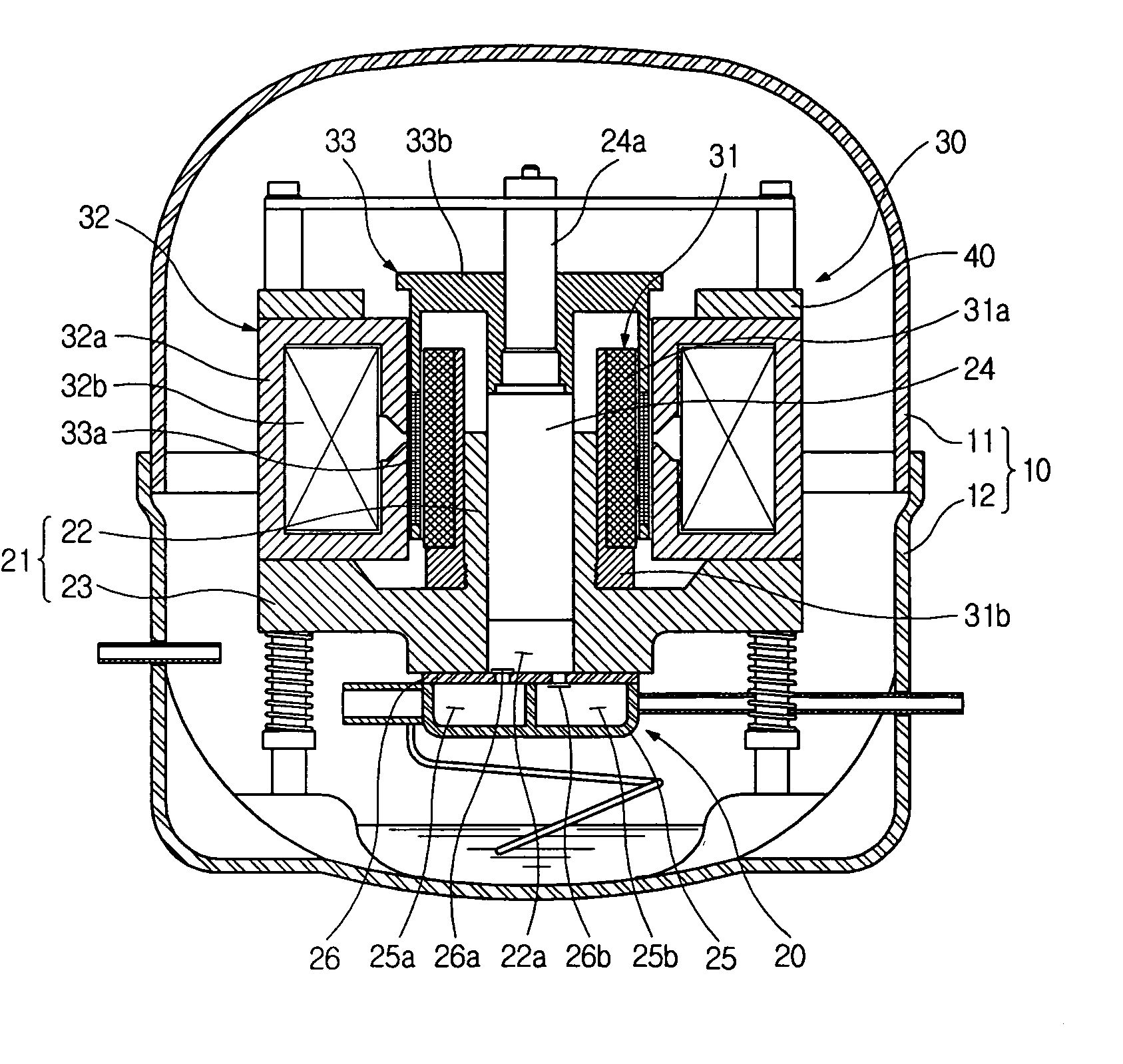
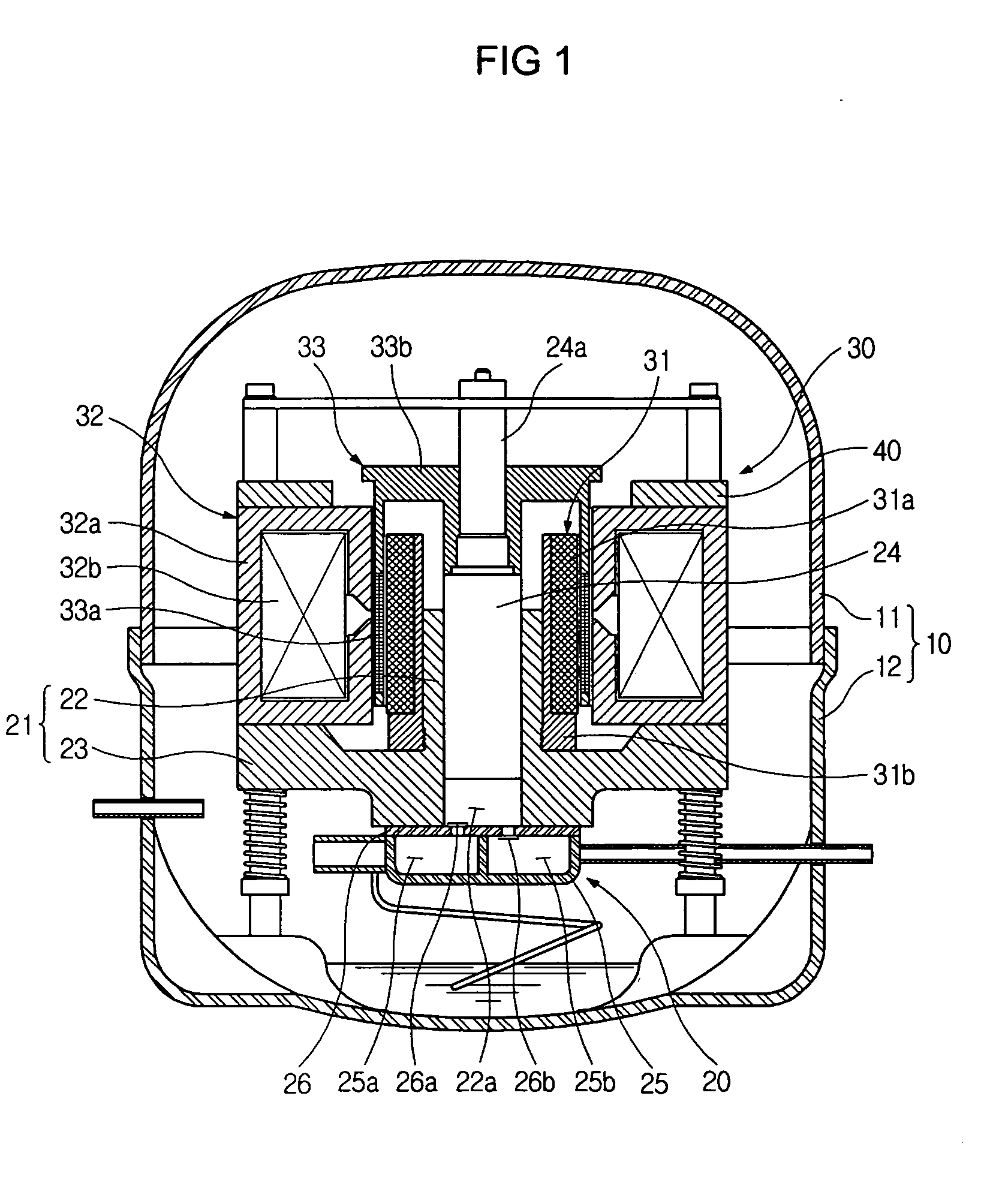
[0020]FIG. 1 is a cross-section of an entire construction of a linear compressor, according to the present invention.

[0021] Referring to FIG. 1, the linear compressor of the present invention includes a closed container 10 configured to form a closed structure by combining an upper container 11 with a lower container 12, a compression unit 20 provided in the closed container 10 to compress a refrigerant, and a drive unit 30 adapted to provide power to the compression unit 20.

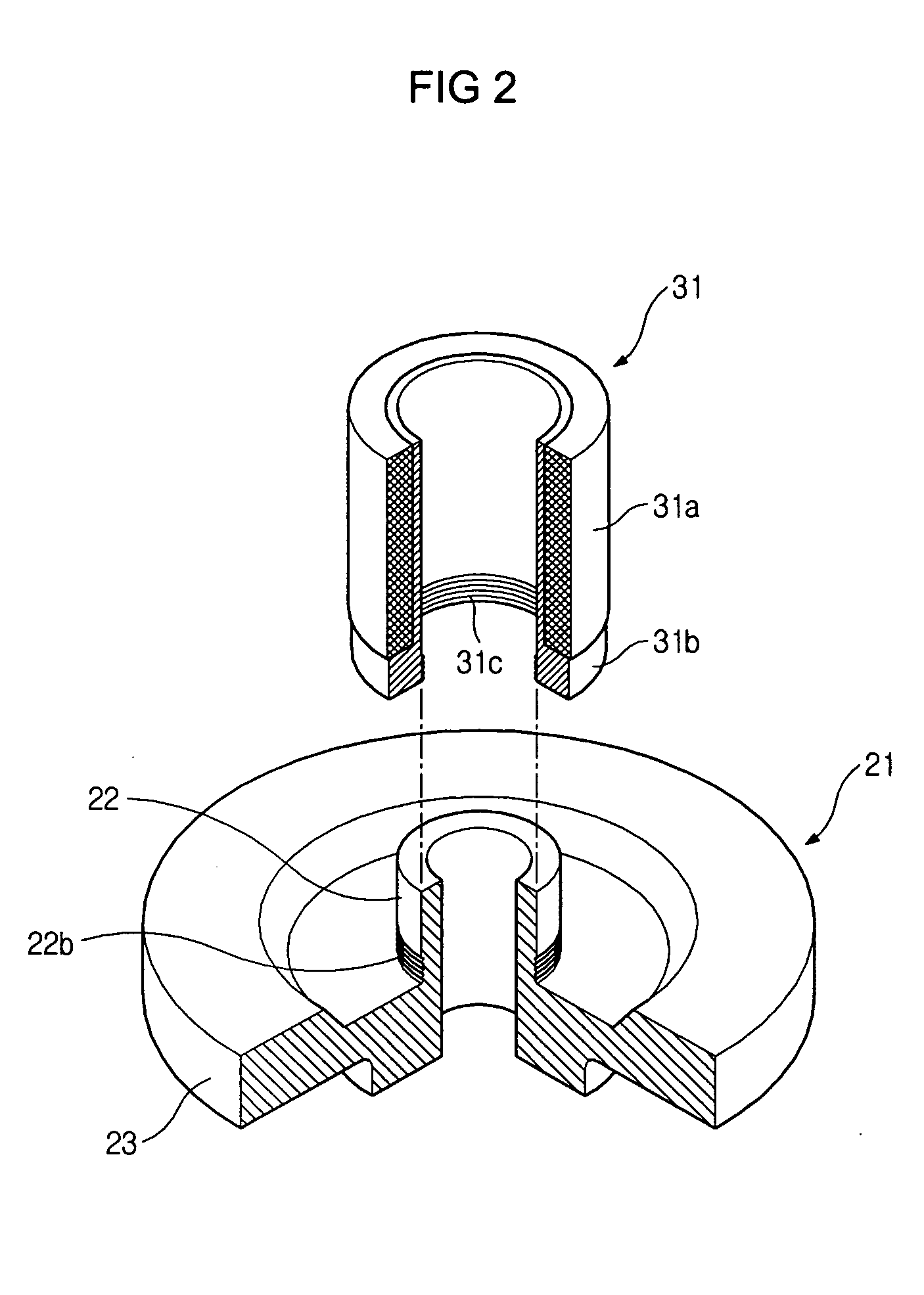
[0022] The compression unit 20 includes a cylinder block 21 into which a cylinder 22 defining a compression chamber 22a and a support part 23 extending outward from a circumference of a lower part of the cylinder 22 are integrated, and a piston 24 which is placed in the compre...


PUM


Abstract

The present invention relates to a linear compressor. In the linear compressor, a holder 31b is combined with a cylinder 22 in an interlocking fashion by forming a first threaded part 31c on an inner surface of the holder 31b, the outer side of which on an inner core 31a is mounted, and a second threaded part 22b on an outer surface of the cylinder 22 to correspond to the first threaded part 31c. That is, screws are not required when the cylinder 22 and the holder 31b are combined with each other, thus preventing the cylinder 22 from being deformed by a fastening torque of the screws.

Description

CROSS-REFERENCE TO RELATED APPLICATION [0001] This application claims the benefit of Korean Patent Application No. 2003-83189, filed Nov. 21, 2003 in the Korean Intellectual Property Office, the disclosure of which is incorporated herein by reference. BACKGROUND OF THE INVENTION [0002] 1. Field of the Invention [0003] The present invention relates, in general, to a linear compressor and, more particularly, to a linear compressor having an inner core combined with an outside of a cylinder. [0004] 2. Description of the Related Art [0005] Generally, a linear compressor is used to compress a refrigerant of a refrigeration apparatus, such as a refrigerator and an air conditioner, and refers to a compressor adopting a linear motor, which reciprocates linearly, as a drive means to reciprocate a piston. [0006] A conventional linear compressor includes a compression unit to compress the refrigerant in a closed container, and a drive unit to provide power to the compression unit. [0007] The c...

Claims


Application Information

Patent Timeline
IPC IPC(8): F04B39/00F04B17/04F04B35/04
CPCF04B35/045F04B39/14H02K1/12H02K15/02H02K41/02
Inventor LEE, TAE KYUNG
Owner SAMSUNG GWANGJU ELECTRONICS CO LTD
Why Eureka
Try Eureka