Fuel cell system for an automotive vehicle

a fuel cell and automotive technology, applied in the field of fuel cell systems, can solve the problems of large electric power required for the automotive vehicle, the inability to install a heavy and expensive reformer on the vehicle, and the general dissatisfactory performance of the reformer, so as to achieve the effect of convenient installation in the automotive vehicl

Inactive Publication Date: 2005-05-26
DENSO CORP
View PDF6 Cites 19 Cited by
  • Summary
  • Abstract
  • Description
  • Claims
  • Application Information

AI Technical Summary

Benefits of technology

[0009] In view of the above-described problems, the present invention has an object to provide a fuel cell system which is easily installable in an automotive vehicle without newly providing a space for a fuel container of the fuel cell.

Problems solved by technology

Accordingly, a great amount of electric power is required for the automotive vehicle.
However, according to such a fuel cell system, it is necessary to install a heavy and expensive reformer on a vehicle.
Furthermore, the reformer is generally dissatisfactory in its performance because it cannot quickly and accurately respond to frequent accelerating / decelerating and stopping operations or other load changes occurring in the automotive vehicle.
However, the fuel cell system incorporating the DMFC requires an additional container to be installed in an automotive vehicle for storing methanol or comparable fuel.
Securing a sufficient space for this container is not easy because an available space in an automotive vehicle is limited.

Method used


Image

  • Fuel cell system for an automotive vehicle
  • Fuel cell system for an automotive vehicle
  • Fuel cell system for an automotive vehicle

Examples


first embodiment

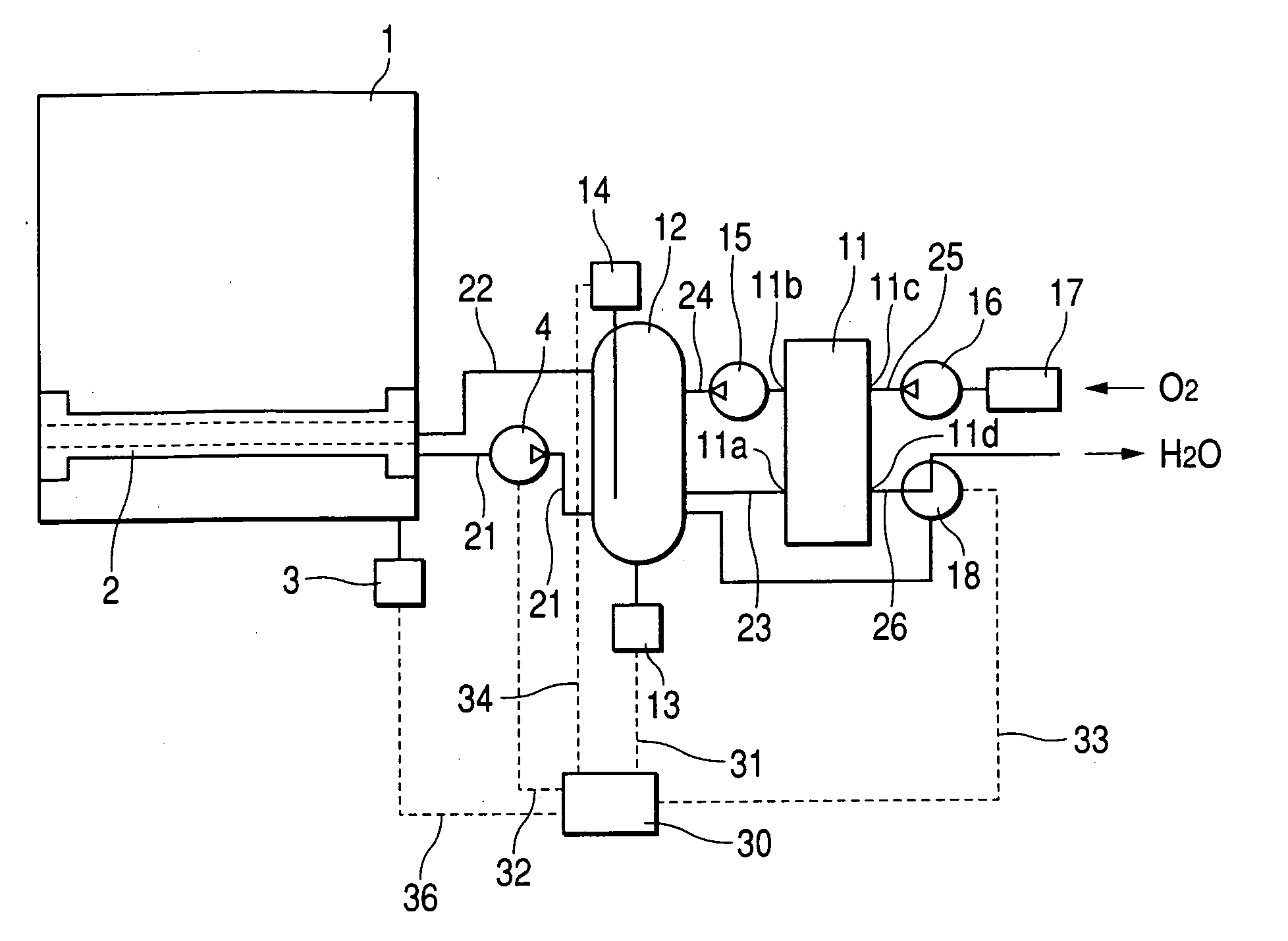
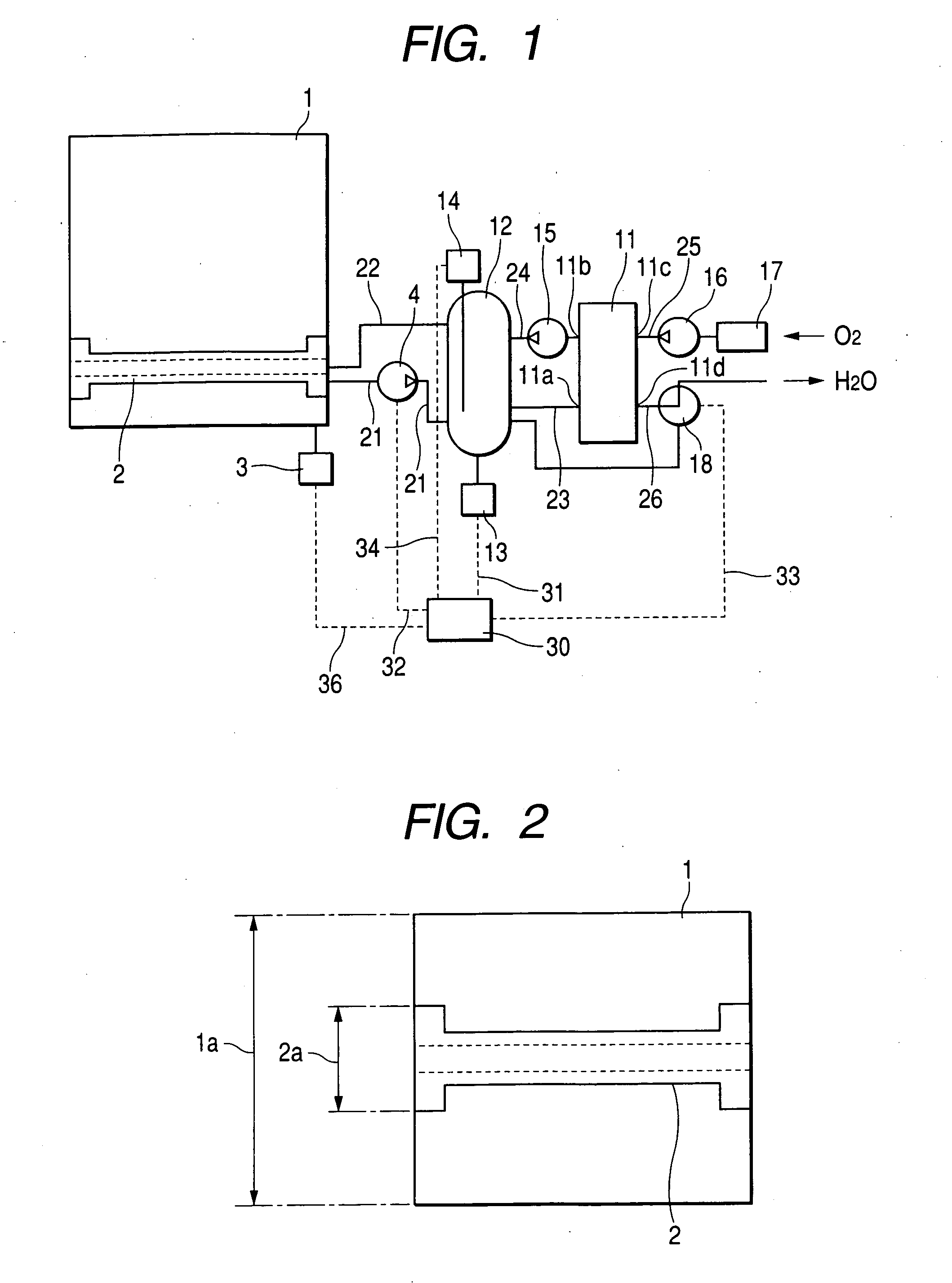
[0028]FIG. 1 shows the arrangement of a fuel cell system in accordance with a first embodiment of the present invention.

[0029] This fuel cell system is usable as an auxiliary power source for an automotive vehicle. For example, this fuel cell system is effectively used to prevent a battery from going flat in a long-lasting stopped condition of an automotive vehicle.

[0030] As shown in FIG. 1, this fuel cell system includes a windshield washer container 1, a permeable membrane unit 2, a first methanol concentration sensor 3, a first circulating pump 4, a controller 30, a fuel cell 11, a methanol tank 12, a second methanol concentration sensor 13, a liquid amount meter 14, and a switching valve 18.

[0031] The windshield washer container 1 stores windshield washer fluid used for cleaning a windshield glass of an automotive vehicle. The windshield washer container 1 is, for example, a normal windshield washer container which has been conventionally employed for the automotive vehicles ...

second embodiment

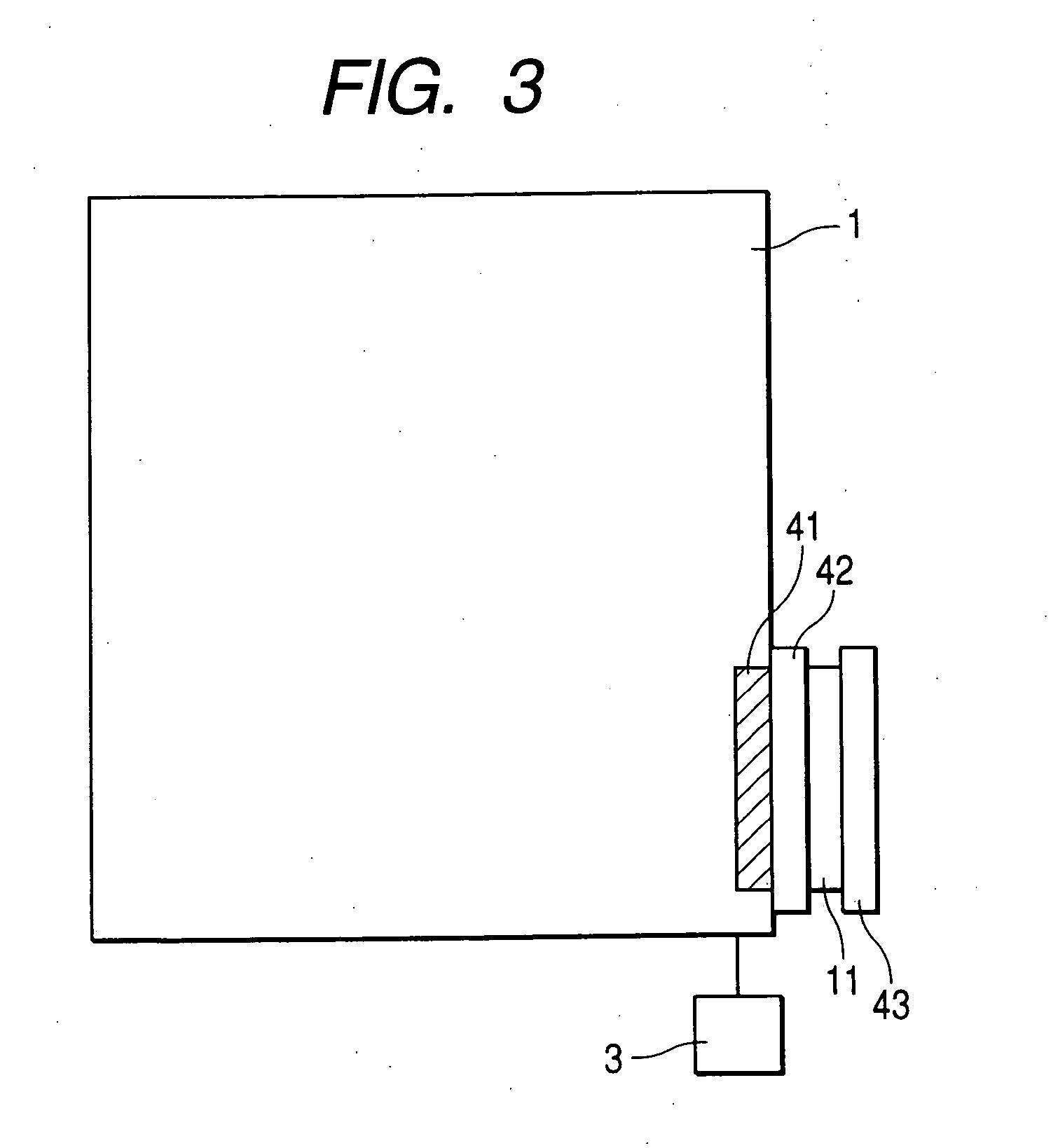
[0058]FIG. 3 shows the arrangement of a fuel cell system in accordance with a second embodiment of the present invention. The components and portions in FIG. 3 are denoted by the same reference numerals as those of FIG. 1 when they are identical with those of the fuel cell system according to the first embodiment.

[0059] According to the first embodiment, the fuel cell system includes the first circulating pump 4, the second circulating pump 15, and the air pump 16 to forcibly supply methanol and air to the fuel cell 11. The second embodiment is different from the first embodiment in that the first circulating pump 4, the second circulating pump 15, and the air pump 16 are omitted. In other words, the second embodiment provides a fuel cell system which is capable of introducing methanol and air into the fuel cell 11 based on natural diffusion.

[0060] As shown in FIG. 3, the fuel cell system of this embodiment includes a permeable membrane 41 provided on a side surface of the windshi...

third embodiment

[0068]FIG. 4 shows the arrangement of a fuel cell system in accordance with a third embodiment of the present invention. The components and portions in FIG. 4 are denoted by the same reference numerals as those of FIG. 3 when they are identical with those of the fuel cell system according to the second embodiment. The fuel cell system according to this embodiment is different from the fuel cell system according to the second embodiment in the arrangement of the windshield washer container1.

[0069] The windshield washer container 1 of this embodiment is a general type. However, as shown in FIG. 4, the windshield washer container 1 has a partition 51 to divide the inside space into two chambers, i.e. a methanol container 52 and a surfactant container 53.

[0070] The methanol container 52 stores methanol and water, while the surfactant container 53 stores surfactant. The methanol and the surfactant of this embodiment correspond to the windshield washer fluid of the present invention.

[0...


PUM

PropertyMeasurementUnit
electric poweraaaaaaaaaa
permeableaaaaaaaaaa
widthaaaaaaaaaa

Abstract

A fuel cell system includes a windshield washer container 1 storing windshield washer fluid, a permeable membrane unit 2 provided inside the windshield washer container 1, and a fuel cell 11. The permeable membrane unit 2 has the capability of extracting methanol from the windshield washer fluid. The extracted methanol is directly used as the fuel for the fuel cell 11. The windshield washer container 1 has the size comparable with or less than that of a conventional windshield washer container.

Description

CROSS-REFERENCE TO RELATED APPLICATION [0001] This application is based upon and claims the benefit of priority of the Japanese Patent Application No. 2003-392336, filed on Nov. 21, 2003, so that the description of which is incorporated herein by reference. BACKGROUND OF THE INVENTION [0002] The present invention relates to a fuel cell system which is, for example, preferably used as an auxiliary power source of an automotive vehicle. [0003] Automotive vehicles are recently equipped with many electronic devices. Accordingly, a great amount of electric power is required for the automotive vehicle. In general, the automotive vehicle installs an alternator to generate electric power and a battery to store electric power. Meanwhile, various kinds of fuel cells are already proposed as effective devices capable of supplying electric power to the automotive vehicles. [0004] One of the conventionally known fuel cells is a polyelectrolyte fuel cell (hereinafter, referred to as PEFC). Further...

Claims


Application Information

Patent Timeline
Patent Type & Authority Applications(United States)
IPC IPC(8): H01M8/10H01M8/00H01M8/04
CPCH01M8/04194H01M8/0687H01M8/1011Y02T90/32Y02E60/523Y02E60/522H01M2250/20Y02E60/50Y02T90/40
Inventor OSHIMA, HISAYOSHIOKAMOTO, KUNIO
Owner DENSO CORP
Why Eureka
Try Eureka