Breath monitor

a monitor and breath technology, applied in the field of breath monitors, can solve the problems of inability to detect the hypopnea of patients with high accuracy, and the monitor cannot accurately detect the breath signal, so as to achieve the effect of improving the accuracy of the breath signal and high accuracy

Active Publication Date: 2005-05-26
DENSO CORP
View PDF5 Cites 33 Cited by
  • Summary
  • Abstract
  • Description
  • Claims
  • Application Information

AI Technical Summary

Benefits of technology

[0009] In this case, the sensor outputting the sensor signal corresponding to the breath of the human can be selected appropriately so that the breath signal is obtained with high accuracy. Therefore, the accuracy of the breath signal is improved. Thus, the breath monitor monitors breath of a human accurately.

Problems solved by technology

In this case, the monitor cannot detect the breath signal accurately.
However, the monitor according to the prior art cannot detect the hypopnea of the patient with high accuracy.

Method used


Image

  • Breath monitor
  • Breath monitor
  • Breath monitor

Examples


first embodiment

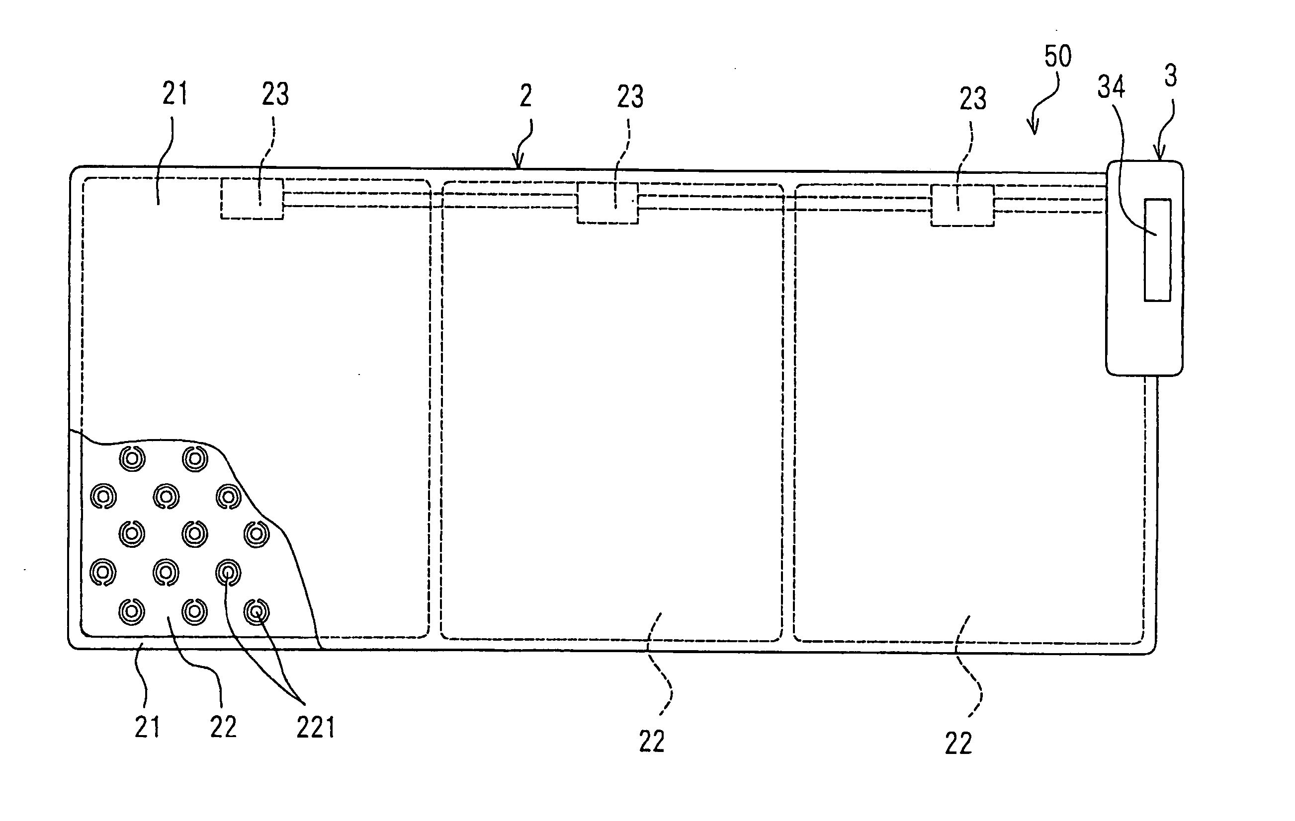
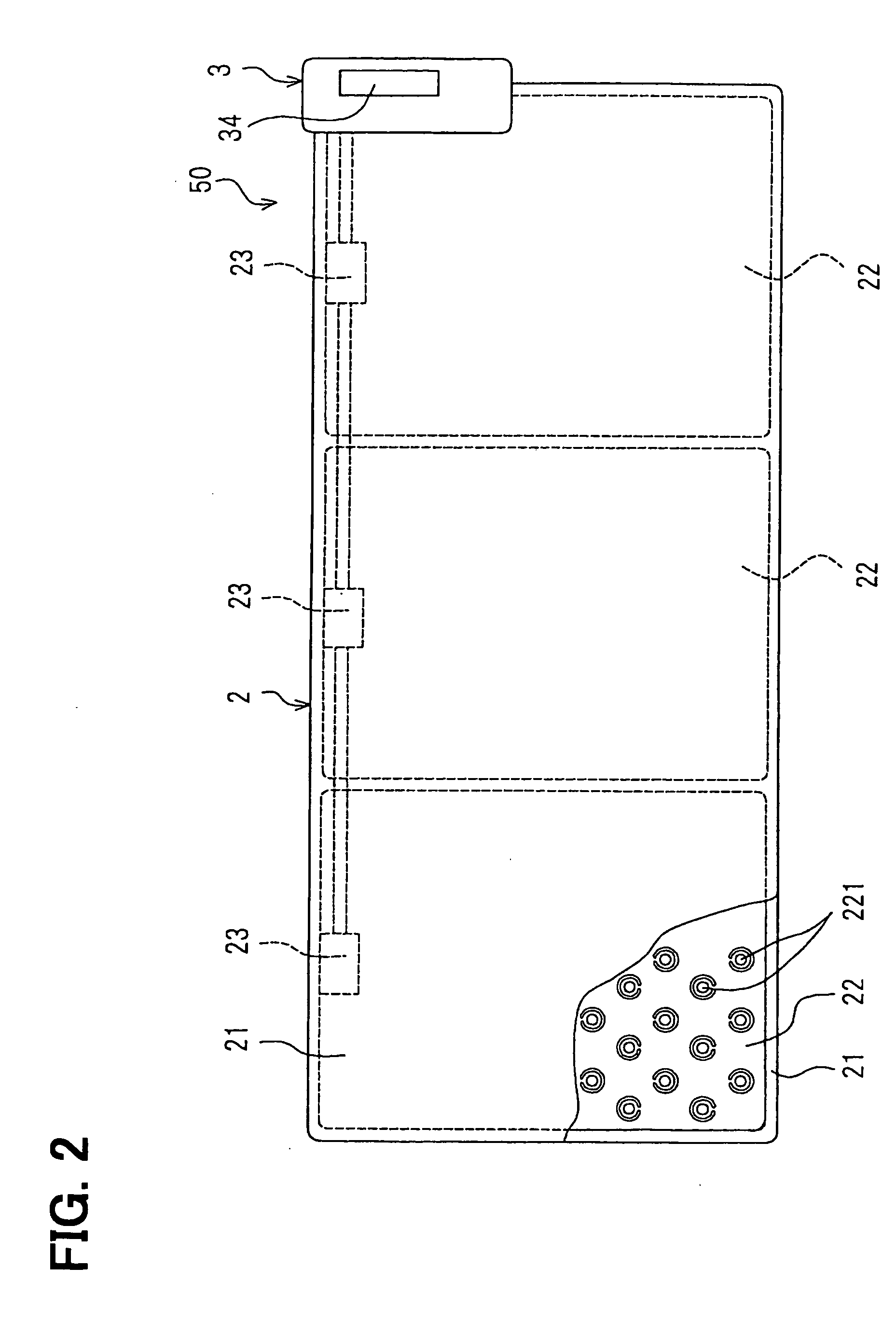
[0033] A breath monitor according to a first embodiment of the present invention includes a plurality of sensors for detecting a load or a vibration derived from a human, i.e., a patient lying on a bed and for outputting a sensor signal corresponding to the load or the vibration; and breath signal computation means. For example, the sensor is a pressure sensor so that the sensor detects the load derived from a weight of the human. Or, the sensor is a vibration sensor so that the sensor detects the load derived form a vibration of a body movement of the human. The sensors are disposed under the human with a predetermined arrangement. The breath signal computation means converts the sensor signal to a frequency domain, selects the sensor on the basis of the converted sensor signal, and computes the breath signal on the basis of the sensor signal outputted from the selected sensor. Here, the sensor is arranged with the predetermined arrangement. The predetermined arrangement is, for ex...

second embodiment

[0083] In step S520 in the quick movement determination process shown in FIG. 11, it is determined whether the amplitude of one cycle is twice larger than the amplitude of the former or latter cycle waveform. Further, additional step can be added after step S520. In the additional step, it is determined whether the one cycle having the amplitude twice larger than the amplitude of the former or latter cycle waveform is repeated periodically. When multiple cycles having the amplitude twice larger than the amplitude of the former or latter cycle are disposed in 256 cycles, and the cycles are repeated periodically, the patient may be a periodic leg movement disorder (i.e., PLMD). In this case, the monitor can distinguish the PLMD.

third embodiment

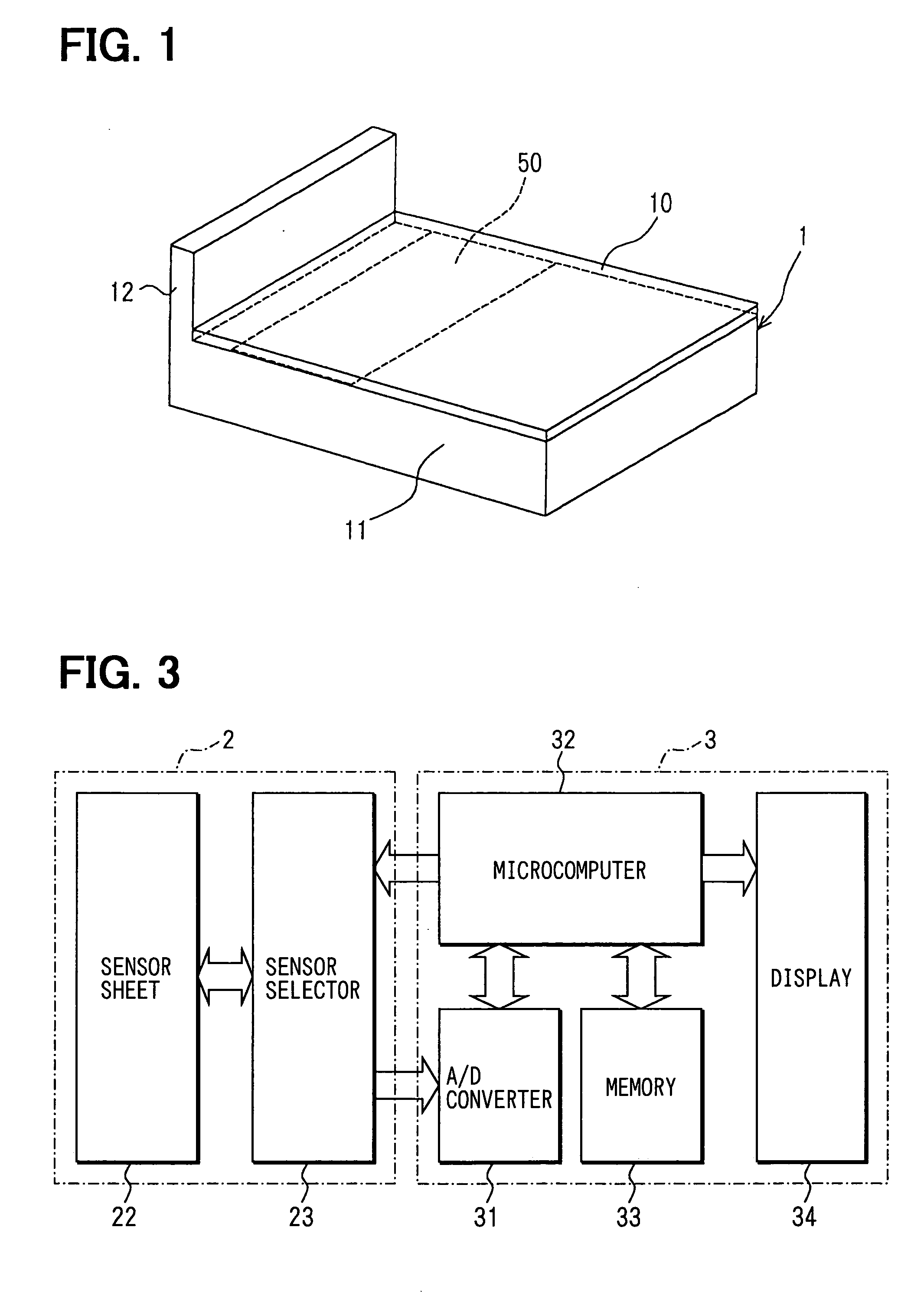
[0084] The inventors have preliminary studied about detection equipment for detecting apnea state or hypopnea of a human so that a person such as a doctor or a nurse diagnoses apnea syndrome of the human while sleeping. The detection equipment includes a sensor sheet having multiple pressure sensors disposed under the bedclothes, a controller, a display for showing the number of breathing of the patient and / or showing the number of decreasing of oxygen saturation of blood of the patient. Each pressure sensor detects a load, i.e., pressure of the patient and outputs a load signal to the controller so that the controller computes a breath motion signal as a breath signal corresponding to the breathing of the patient. The breath motion signal has a frequency range corresponding to the number of the breathing. When oxygen saturation of blood of the patient is decreased, amplitude of the breath motion signal is changed particularly. Thus, a certain changing pattern of the amplitude of th...


PUM


Abstract

A breath monitor includes: a plurality of sensors for detecting a load derived from a human lying on a bed and for outputting a sensor signal corresponding to the load; and breath signal computation means. The sensors are disposed under the human with a predetermined arrangement. The breath signal computation means converts each sensor signal to a frequency domain so that a spectrum of each sensor signal is obtained, selects the sensors on the basis of the converted sensor signals, and computes a breath signal on the basis of the sensor signals outputted from the selected sensors.

Description

CROSS REFERENCE TO RELATED APPLICATIONS [0001] This application is based on Japanese Patent Applications No. 2003-395598 filed on Nov. 26, 2003, and No. 2004-7237 filed on Jan. 14, 2004, the disclosures of which are incorporated herein by reference. FIELD OF THE INVENTION [0002] The present invention relates to a breath monitor for monitoring breath of a human. BACKGROUND OF THE INVENTION [0003] A breath monitor for monitoring breath of a human while sleeping is disclosed in Japanese Patent Application Publication No. 2001-3.7742, which corresponds to U.S. Pat. No. 6,450,957. Specifically, the monitor is suitably used for diagnosing a patient having a respiratory disease. A sensor of the monitor is disposed under bedclothes to have a predetermined arrangement. The monitor includes multiple loading sensors for detecting an applied load of the patient. Each sensor outputs a load signal (i.e., a weight signal) as a sensor signal in accordance with the applied load. A breath signal is c...

Claims


Application Information

Patent Timeline
Patent Type & Authority Applications(United States)
IPC IPC(8): A61B5/103A61B5/11A61B5/113
CPCA61B5/103A61B5/1126A61B5/113A61B5/4806A61B2562/046A61B5/6887A61B5/721A61B2562/0247A61B5/4818
Inventor NAKATANI, HIROTOOZAKI, NORIYUKIYANAI, KENICHI
Owner DENSO CORP
Why Eureka
Try Eureka