Thermal measurments of electronic devices during operation

a technology of electronic devices and thermal measurements, applied in the field of microprocessors, can solve the problems of uneven distribution of heat load on the microprocessor, severe cooling problem, uneven cooling effect,

Inactive Publication Date: 2005-05-26
IBM CORP
View PDF12 Cites 505 Cited by
  • Summary
  • Abstract
  • Description
  • Claims
  • Application Information

AI Technical Summary

Benefits of technology

[0008] Briefly, in accordance with the present invention, disclosed is a system and method for measuring the thermal distributions of a microprocessor during operation. In an embodiment of the present invention, the system includes a microprocessor, a heat sink adjacent to the microprocessor and an electrical-insulating layer disposed preferably on the heat sink so as to isolate the sensing circuitry and the heat sink. The system further includes a plurality of thermal sensors located adjacent to the electrical-insulating layer, each of the plurality of thermal ...

Problems solved by technology

The cooling problem has become quite severe due to increased circuit density within contemporary microprocessors and the accompanying leakage currents that result.
As a further complication, the heat load on a microprocessor, which depends on the workload of the microprocessor, is unevenly distributed over the area of the microprocessor die.
Without detailed thermal knowledge of a microprocessor during operation, it is impossible to guarantee that the microprocessor will withstand the temperatures to which it will be subjected in the normal course of operation.
To date, there is no known technique for measuring the thermal distribution of a fully operational microprocessors with heat flux densities of larger than approximately 10 W/cm2.
One reason for this lack of techniques is due to the fact that cooling systems...

Method used


Image

  • Thermal measurments of electronic devices during operation
  • Thermal measurments of electronic devices during operation
  • Thermal measurments of electronic devices during operation

Examples


Embodiment Construction

[0023] It should be understood that these embodiments are only examples of the many advantageous uses of the innovative teachings herein. In general, statements made in the specification of the present application do not necessarily limit any of the various claimed inventions. Moreover, some statements may apply to some inventive features but not to others. In general, unless otherwise indicated, singular elements may be in the plural and vice versa with no loss of generality. In the drawing like numerals refer to like parts through several views.

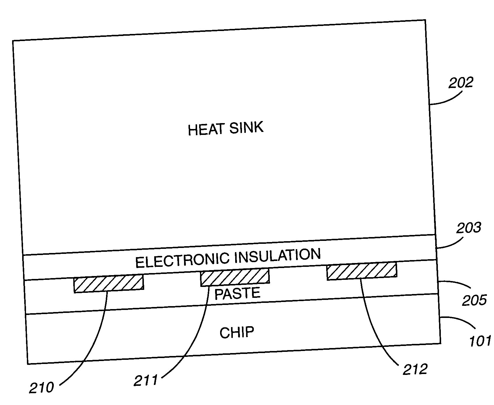
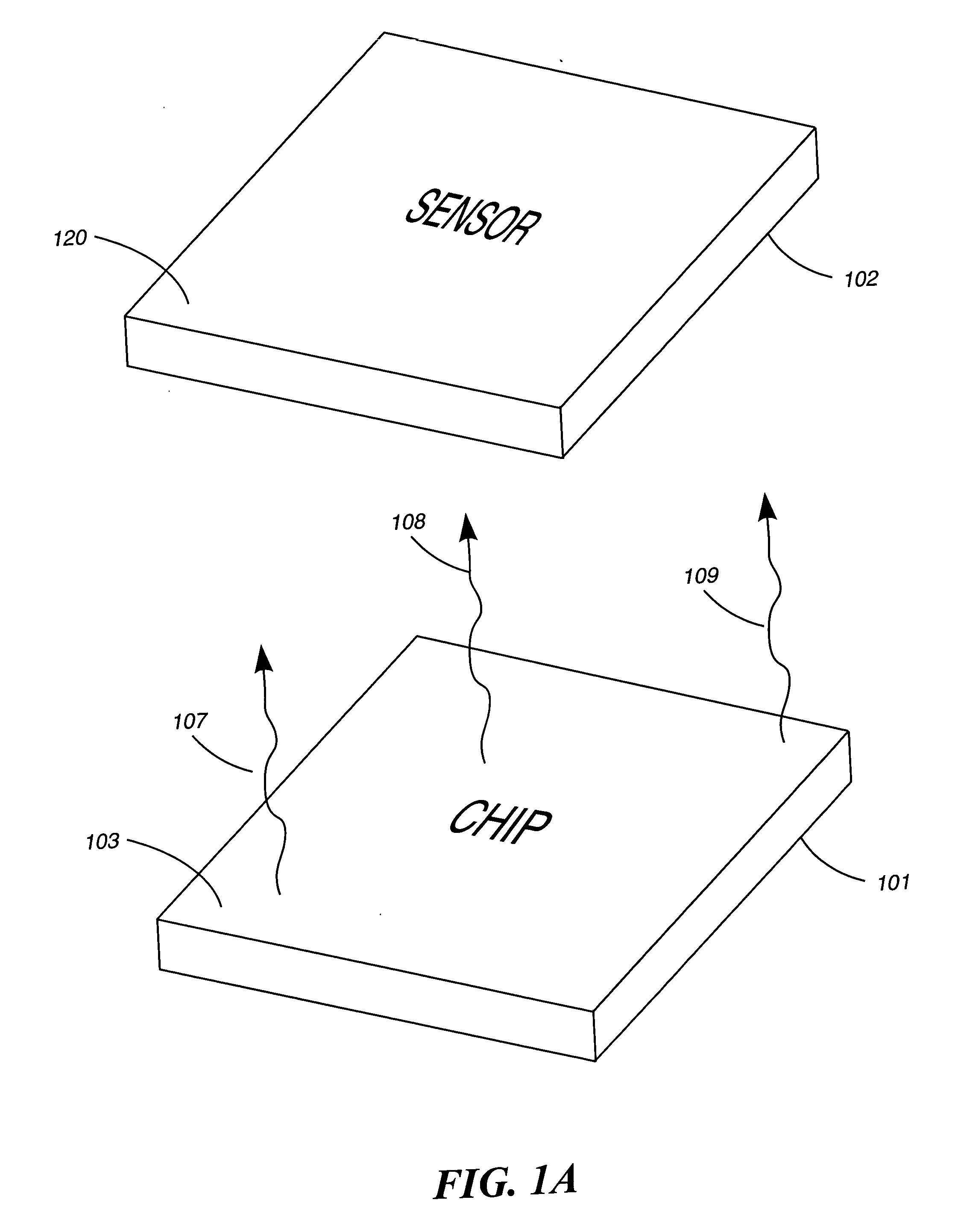
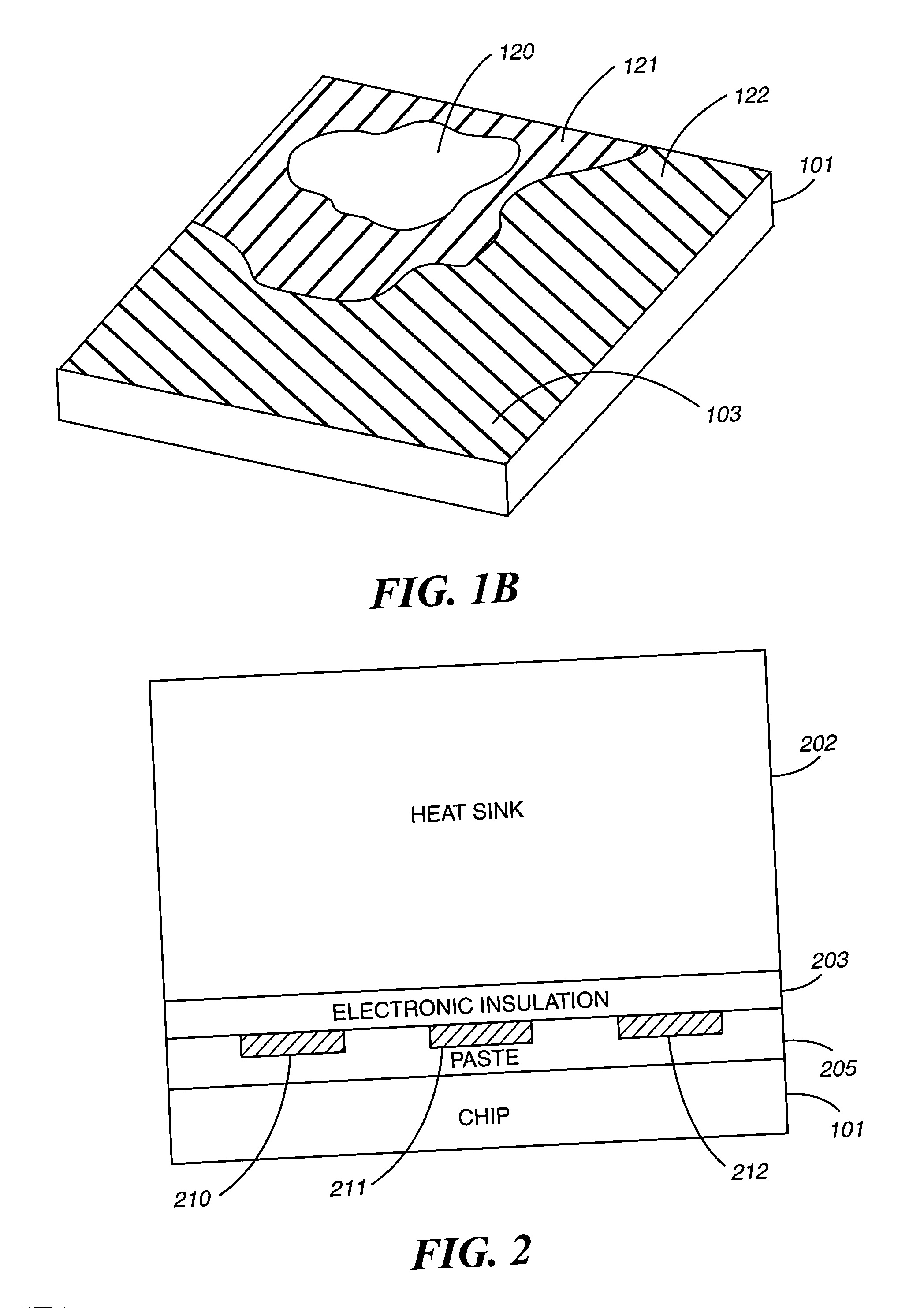
[0024] The present invention, according to a preferred embodiment, overcomes problems with the prior art by providing an efficient and easy-to-implement system and method for measuring the thermal distributions of a microprocessor during operation.

Overview

[0025] In order to ascertain the thermal distributions of a microprocessor under operating conditions, several embodiments are disclosed to determine the microprocessor thermal properti...


PUM


Abstract

A system and method for measuring thermal distributions of an electronic device during operation is disclosed. The system includes an electronic device, a heat sink adjacent to the electronic device and an electrical-insulating layer disposed on the electronic device so as to separate the electronic device and the heat sink. The system further includes a plurality of thermal sensors located on the electrical-insulating layer, each of the plurality of thermal sensors in a different location. The plurality of thermal sensors is located within one or more thin film circuit layers disposed adjacent to the electrical insulating layer. The system further includes a module for receiving thermal information from the plurality of thermal sensors during operation of the electronic device. The system further includes a processor coupled to the module for generating a thermal distribution of the electronic device based on the thermal information received from the plurality of thermal sensors.

Description

CROSS-REFERENCED APPLICATIONS [0001] This non-provisional application is related to the following two non-provisional applications: (1) U.S. patent application Ser. No. ______, entitled “TRANSPARENT COOLING DUCT” filed on even date herewith, and (2) U.S. patent application Ser. No. ______, entitled “COOLING OF SURFACE TEMPERATURE OF A DEVICE”, filed on even date herewith, which are hereby commonly assigned to International Business Machines Corporation and which are each hereby separately incorporated by reference in their entirety.PARTIAL WAIVER OF COPYRIGHT [0002] All of the material in this patent application is subject to copyright protection under the copyright laws of the United States and of other countries. As of the first effective filing date of the present application, this material is protected as unpublished material. However, permission to copy this material is hereby granted to the extent that the copyright owner has no objection to the facsimile reproduction by anyon...

Claims


Application Information

Patent Timeline
IPC IPC(8): G01K1/02
CPCG01K1/026
Inventor CHEY, S. JAYHAMANN, HENDRIK F.LACEY, JAMES A.VICHICONTI, JAMESVON GUTFELD, ROBERT J.
Owner IBM CORP
Why Eureka
Try Eureka