System and process for tracking an object state using a particle filter sensor fusion technique

a particle filter and sensor technology, applied in the field of system and process for tracking an object state over time using a particle filter sensor fusion technique, can solve the problems of not performing well for tracking, ssl techniques are good at detecting speakers, and how to do it in a robust and principled way, etc., to achieve precise and discriminating, less computational power and time, and quick and computationally inexpensive estimates

Inactive Publication Date: 2005-05-26
MICROSOFT TECH LICENSING LLC
View PDF5 Cites 12 Cited by
  • Summary
  • Abstract
  • Description
  • Claims
  • Application Information

AI Technical Summary

Benefits of technology

[0012] Once the logical sensors have estimated the object states, they are input into a fuser module, which then combines the estimates to form a proposal function. In one version of the present system and process, these object state estimates are in the form of Gaussian distributions. This allows the tracking function of the sensors to employ simplifying assumptions such as Gaussianality and linearity so as to reduce the processing cost and increase the speed at which the estimates can be generated. While accuracy is sacrificed somewhat at this point in the process due to these assumptions, it is not an issue as will be explained shortly. The action of combining the object state estimate distributions to form the proposal distribution can also involve weighting the estimate distributions using reliability factors associated with each of the logical sensors providing the distributions. In one version of the present system and process, the reliability factors are computed dynamically by re-computing them during each tracking iteration. Essentially, the reliability factor quantifies the degree of similarity between the object state estimate distribution computed by a logical sensor and the final distribution computed for that iteration (as will be described later). The fuser module uses the last computed reliability factor associated with each logical sensor in the next iteration to weight the estimate distribution generated by that sensor as part of combining the object state estimate distributions.
[0014] The verification procedure involves each logical sensor estimating the likelihood of each particle provided by the fuser module. Thus, each logical sensor has two parts-namely an object state tracker for generating the object state estimates and an object state verifier for verifying the particles generated by the fuser module. This architecture has a significant advantage as the likelihood models used by the tracker and verifier can differ. It is desired that the tracker provide quick and computationally inexpensive estimates. Thus the likelihood model employed by a tracker will necessarily be somewhat loose. However, it is desired that the verifier be quite accurate so that any error introduced in the original object state estimate is compensated for by identifying inaccurate particles generated as a result of the original estimates. To this end, the likelihood model employed by the verifier should be more precise and discriminating than that used by the tracker. This is possible since the verifier only needs to verify a given hypothesis, which is much easier than solving the tracking problem and so requires less computational power and time.

Problems solved by technology

But how to do it in a robust and principled way is still an open problem.
Essentially, SSL techniques are good at detecting a speaker, but do not perform well for tracking, especially when the person of interest is not constantly talking.
While the assumptions make the problem tractable, they inherently hinder the robustness of the bottom-up techniques.
There is, however, inefficiency with this paradigm.
For example, because the sensors have verifiers instead of trackers, they do not help the fuser to generate good hypotheses.
The hypotheses are semi-blindly generated [17], and some can represent low-likelihood regions—thus lowering efficiency [10].
Further, in order to cover the state space sufficiently well, a large number of hypotheses are needed, and this requires extensive computing power.
On the other hand, the top-down paradigm does not require simplified assumptions but needs extensive computation because the hypotheses can be very poor.
Furthermore, a common drawback with both paradigms is that they are open-loop systems.
Similarly, in the top-down paradigm, the sensors do not provide cues to the fuser to help generate more effective hypotheses.
Thus the likelihood model employed by a tracker will necessarily be somewhat loose.

Method used


Image

  • System and process for tracking an object state using a particle filter sensor fusion technique
  • System and process for tracking an object state using a particle filter sensor fusion technique
  • System and process for tracking an object state using a particle filter sensor fusion technique

Examples


Embodiment Construction

[0027] In the following description of the preferred embodiments of the present invention, reference is made to the accompanying drawings which form a part hereof, and in which is shown by way of illustration specific embodiments in which the invention may be practiced. It is understood that other embodiments may be utilized and structural changes may be made without departing from the scope of the present invention.

1.0 The Computing Environment

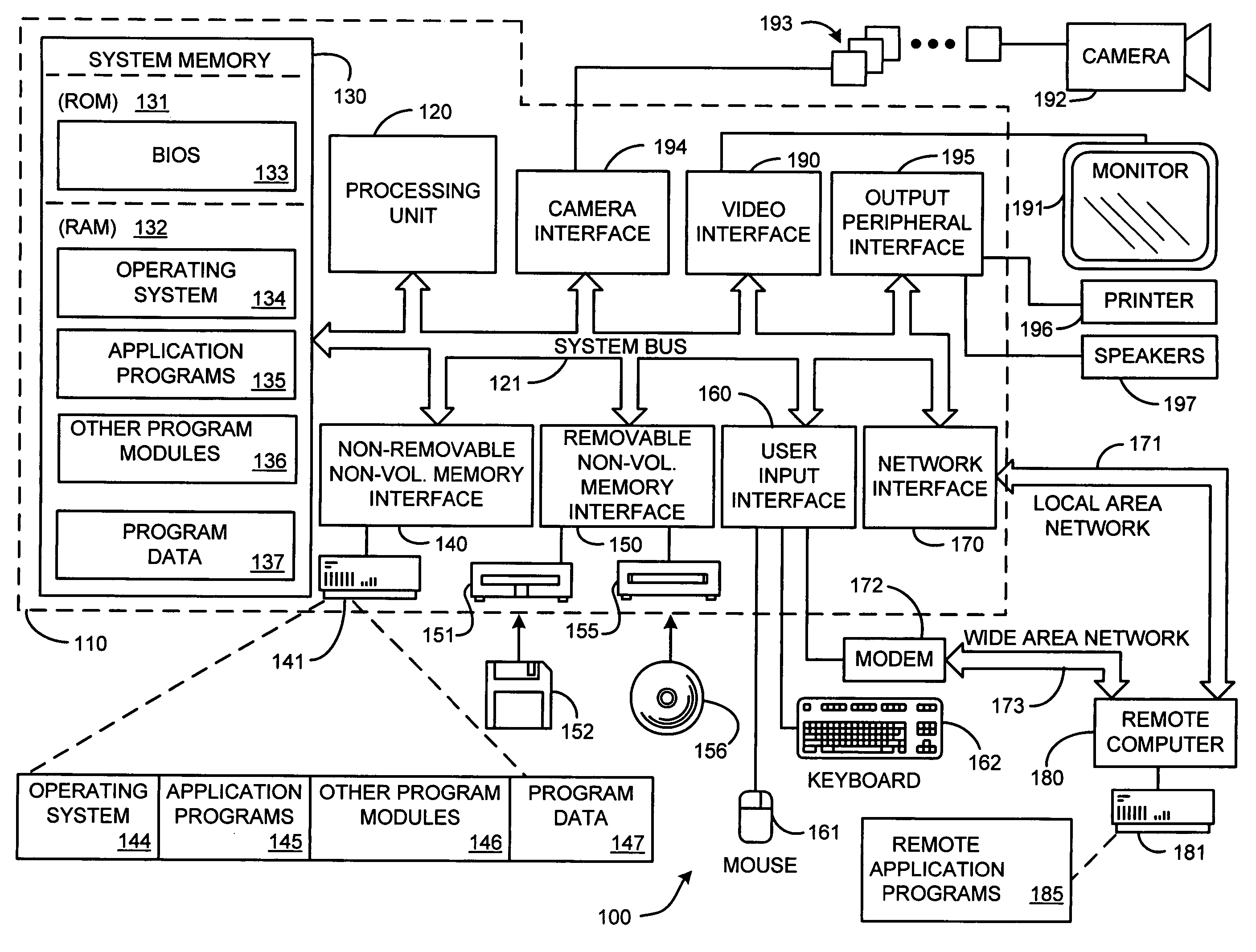
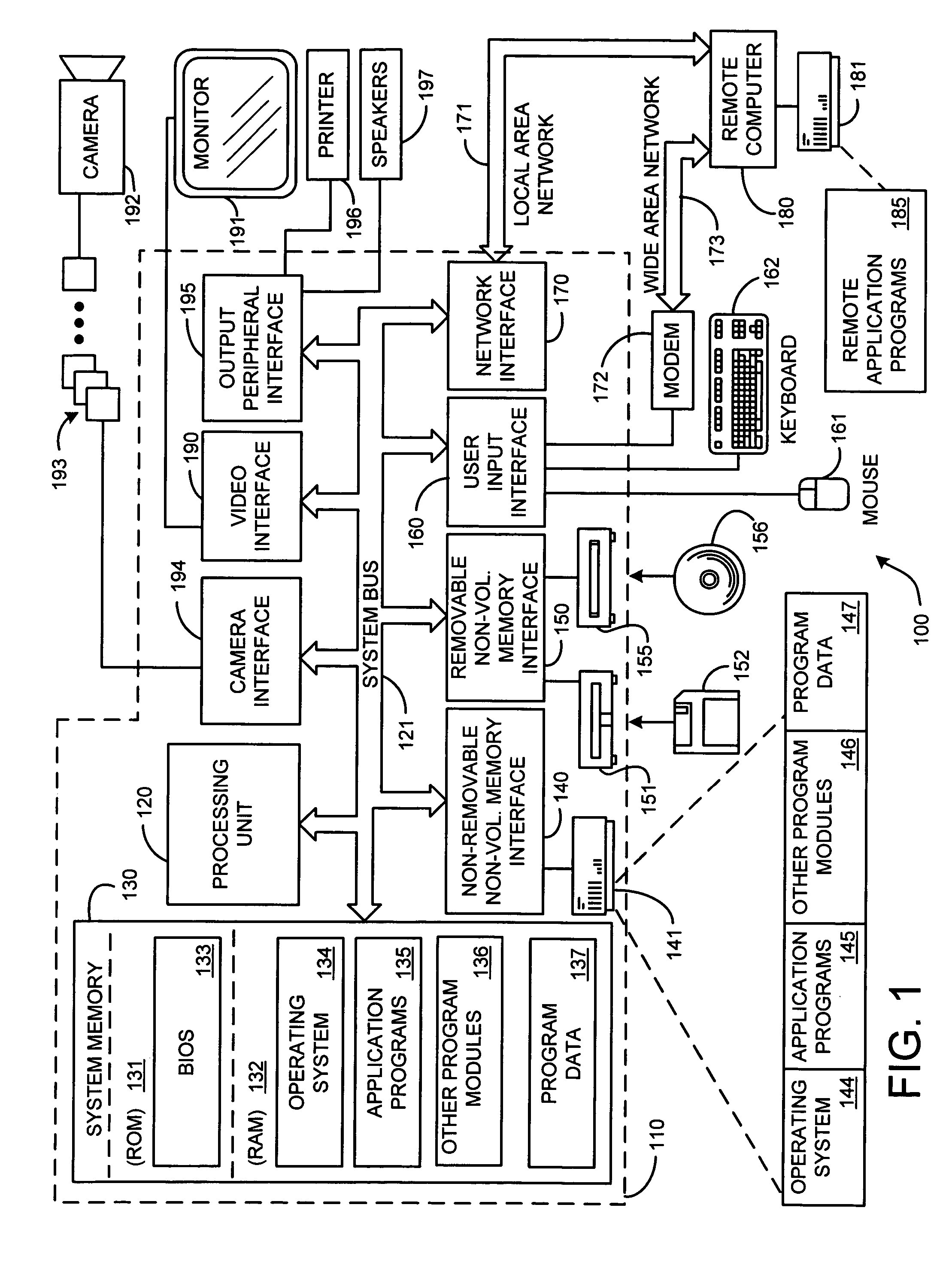
[0028] Before providing a description of the preferred embodiments of the present invention, a brief, general description of a suitable computing environment in which the invention may be implemented will be described. FIG. 1 illustrates an example of a suitable computing system environment 100. The computing system environment 100 is only one example of a suitable computing environment and is not intended to suggest any limitation as to the scope of use or functionality of the invention. Neither should the computing environment 100 be int...


PUM


Abstract

A system and process for tracking an object state over time using particle filter sensor fusion and a plurality of logical sensor modules is presented. This new fusion framework combines both the bottom-up and top-down approaches to sensor fusion to probabilistically fuse multiple sensing modalities. At the lower level, individual vision and audio trackers can be designed to generate effective proposals for the fuser. At the higher level, the fuser performs reliable tracking by verifying hypotheses over multiple likelihood models from multiple cues. Different from the traditional fusion algorithms, the present framework is a closed-loop system where the fuser and trackers coordinate their tracking information. Furthermore, to handle non-stationary situations, the present framework evaluates the performance of the individual trackers and dynamically updates their object states. A real-time speaker tracking system based on the proposed framework is feasible by fusing object contour, color and sound source location.

Description

BACKGROUND [0001] 1. Technical Field [0002] The invention is related to systems and processes for tracking an object state over time using sensor fusion techniques, and more particularly to such a system and process having a two-level, closed-loop, particle filter sensor fusion architecture. [0003] 2. Background Art [0004] Sensor fusion for object tracking has become an active research topic during the past few years. But how to do it in a robust and principled way is still an open problem. The problem is of particular interest in the context of tracking the location of a speaker. Distributed meetings and lectures have been gaining in popularity [4, 14]. A key technology component in these systems is a reliable speaker tracking module. For instance, if the system knows the speaker location, it can dynamically point a camera so that the speaker stays within the view of a remote audience. There are commercial video conferencing systems that provide speaker tracking based on audio soun...

Claims


Application Information

Patent Timeline
Patent Type & Authority Applications(United States)
IPC IPC(8): G06T7/20G10L21/02
CPCG10L2021/02166G06T7/208G06T7/277
Inventor RUI, YONGCHEN, YUNQIANG
Owner MICROSOFT TECH LICENSING LLC
Why Eureka
Try Eureka