
Methods and apparatus for line system design

a line system and design method technology, applied in the field of line system design techniques, can solve the problems of signal power loss, signal quality degradation, and need for a large amount of bandwidth in the cor

Active Publication Date: 2005-05-26
RPX CORP
View PDF4 Cites 3 Cited by
  • Summary
  • Abstract
  • Description
  • Claims
  • Application Information

AI Technical Summary

Benefits of technology

[0008] The present invention provides line system design techniques for use in

Problems solved by technology

This growth has resulted in a need for a large amount of bandwidth in the core networks of the Internet.
As the signal travels over the fiber, the signal loses its power level due to noise and fiber impairments.
Nonetheless, after some point, the quality of the signal gets so degraded that the signal has to be regenerated.

Method used


Image

  • Methods and apparatus for line system design
  • Methods and apparatus for line system design
  • Methods and apparatus for line system design

Examples


Embodiment Construction

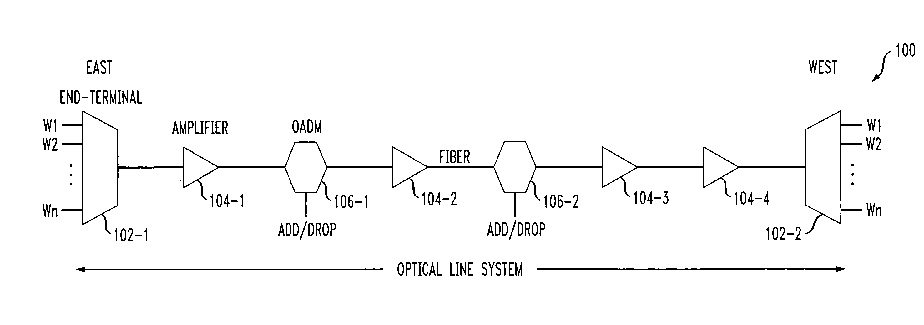
[0019] The following description will illustrate the invention in the context of an exemplary optical line system. It should be understood, however, that the invention is not necessarily limited to use with any particular type of line system. The invention is instead more generally applicable to any line system in which it is desirable to perform efficient routing and coloring operations. As used herein, the term “demand” generally refers to a bandwidth request between nodes. For example, a demand may be made for a wavelength between OADM 106-2 and end terminal 102-2 in FIG. 1.

[0020] Also, while the term “color” is illustratively used herein to refer to a wavelength and the term “coloring” is illustratively used herein to refer to wavelength assignment, the terms are not so limited. That is, the terms “color” and “coloring” may more generally refer to a bandwidth and a bandwidth assignment, respectively. By way of example only, color may refer to an OC-48 bandwidth on an OC-192 cha...


PUM


Abstract

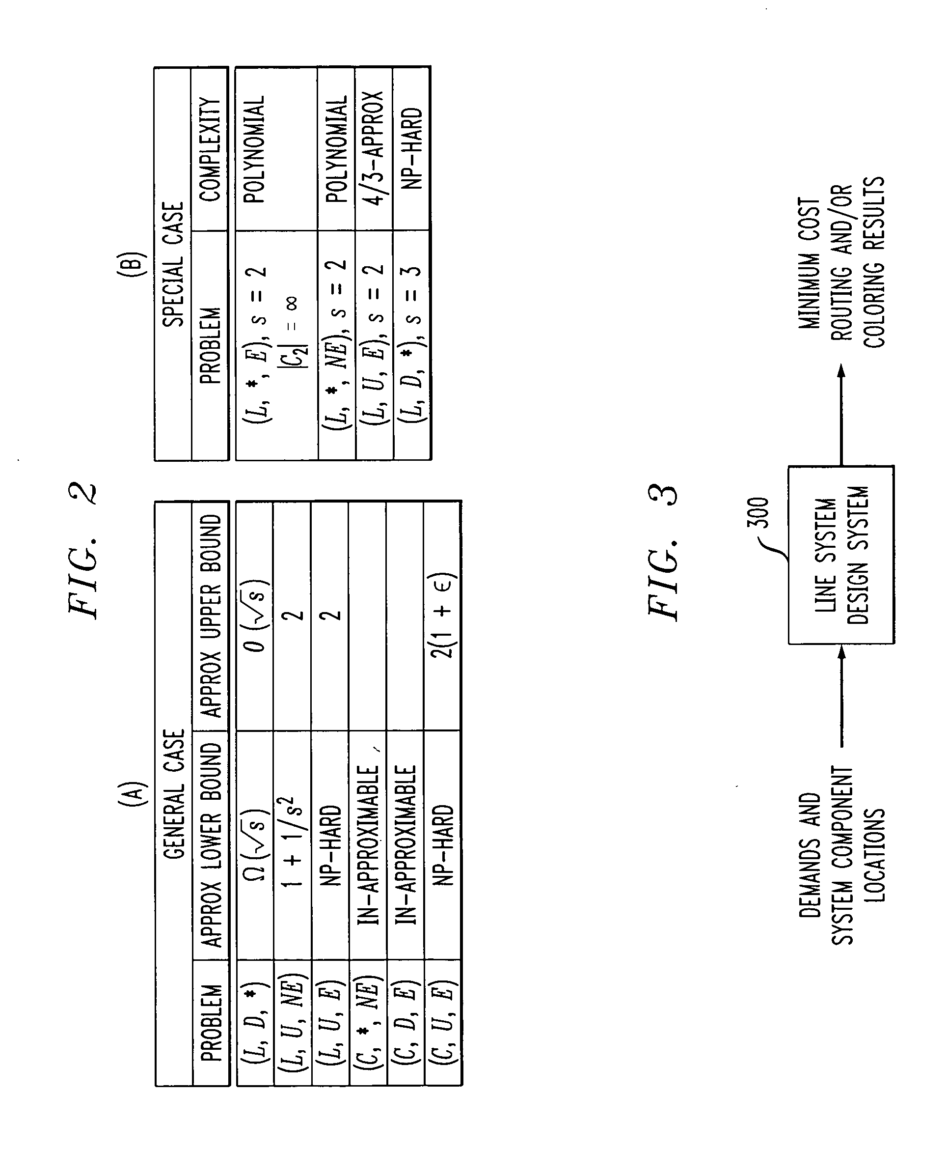
Line system design techniques are provided for use in performing routing and coloring operations associated with one or more demands. In one aspect of the invention, a technique for designing a line system comprises the following steps / operations. A set of one or more demands is obtained for use in computing the line system design. The line system design is then represented as a graph in accordance with a graph coloring operation wherein colors represent bandwidths such that bandwidths are assigned and the one or more demands are routed so as to attempt to achieve a minimum total design cost. The line system being designed may be an optical line system.

Description

FIELD OF THE INVENTION [0001] The present invention relates to line system design techniques and, more particularly, to line system design techniques for use in performing routing and coloring operations associated with one or more demands. BACKGROUND OF THE INVENTION [0002] Over the last several years, there has been a tremendous growth in data traffic spurred primarily by the World Wide Web / Internet. This growth has resulted in a need for a large amount of bandwidth in the core networks of the Internet. [0003] Optical wavelength division multiplexing networks with terabits of bandwidth per fiber form the back-bone of the current generation of the optical Internet. A dense wavelength division multiplexing (DWDM) system partitions the bandwidth of an optical fiber into multiple channels of data rates in tens of gigabits per second (Gbps), each operating at a distinct wavelength. [0004]FIG. 1 illustrates an optical line system. Wavelengths are multiplexed at one end of the line syste...

Claims


Application Information

Patent Timeline
IPC IPC(8): G06F17/10H04J14/02
CPCH04J14/0227H04J14/0241H04J14/0283H04J14/028
Inventor KHAN ALICHERRY, MANSOOR ALIBHATIA, RANDEEP SINGH
Owner RPX CORP
Learn More