System for video digitization and image correction for use with a computer management system

a computer management system and video digitization technology, applied in the field of video digitization and image correction, can solve the problems of reducing the quality of transmitted signals, requiring tremendous cost, and substantial wiring and wire harnessing

Active Publication Date: 2005-05-26
RIIP
View PDF53 Cites 90 Cited by
  • Summary
  • Abstract
  • Description
  • Claims
  • Application Information

AI Technical Summary

Benefits of technology

[0071] Furthermore, it is an object of the present invention to provide a remote network management system that allows high resolution video to be displayed at an extended distance from the computer or server at which the video signals originate.
[0072] Further, it is an objec

Problems solved by technology

However, this alternative requires substantial wiring and wire harnessing, both of which may require tremendous cost.
Additionally, as the distance between the system administrator's user console and the remote computer equipment increases, a decrease in the quality of the transmitted signal often results.
Thus, dedicated cables between the system administrator's user console and remote computer equipment may not be a feasible alternative.
Reducing the amount of digital data transmitted over the communication medium decreases communication time and decreases the required bandwidth.
Most forms of video compression known in the art require complicated calculations.
Since these algorithms are calculation intensive, they either require relatively expensive hardware that performs such calculations quickly or extended transmission times that allow for slower hardware to complete the calculations.
In addition to complexity, many existing video compression techniques are lossy (i.e., they do not transmit all of the video signal information in order to reduce the required bandwidth).
Typically, such lossy techniques either reduce the detail of a video image or reduce the number of colors utilized.
Although reducing the number of col

Method used


Image

  • System for video digitization and image correction for use with a computer management system
  • System for video digitization and image correction for use with a computer management system
  • System for video digitization and image correction for use with a computer management system

Examples


Embodiment Construction

[0090] As required, a detailed illustrative embodiment of the present invention is disclosed herein. However, techniques, systems and operating structures in accordance with the present invention may be embodied in a wide variety of forms and modes, some of which may be quite different from those in the disclosed embodiment. Consequently, the specific structural and functional details disclosed herein are merely representative, yet in that regard, they are deemed to afford the best embodiment for purposes of disclosure and to provide a basis for the claims herein which define the scope of the present invention. The following presents a detailed description of the preferred embodiment (as well as some alternative embodiments) of the present invention.

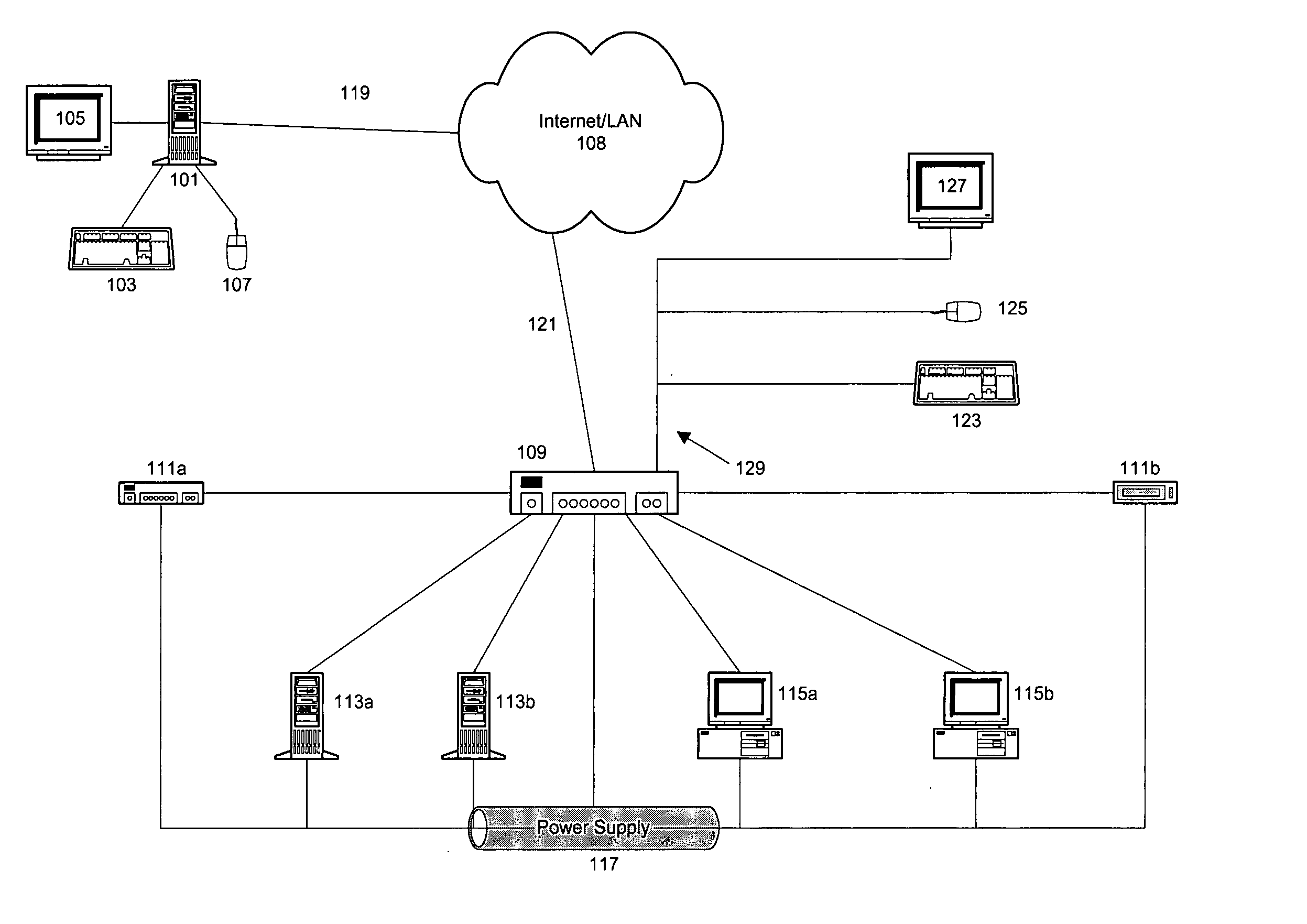
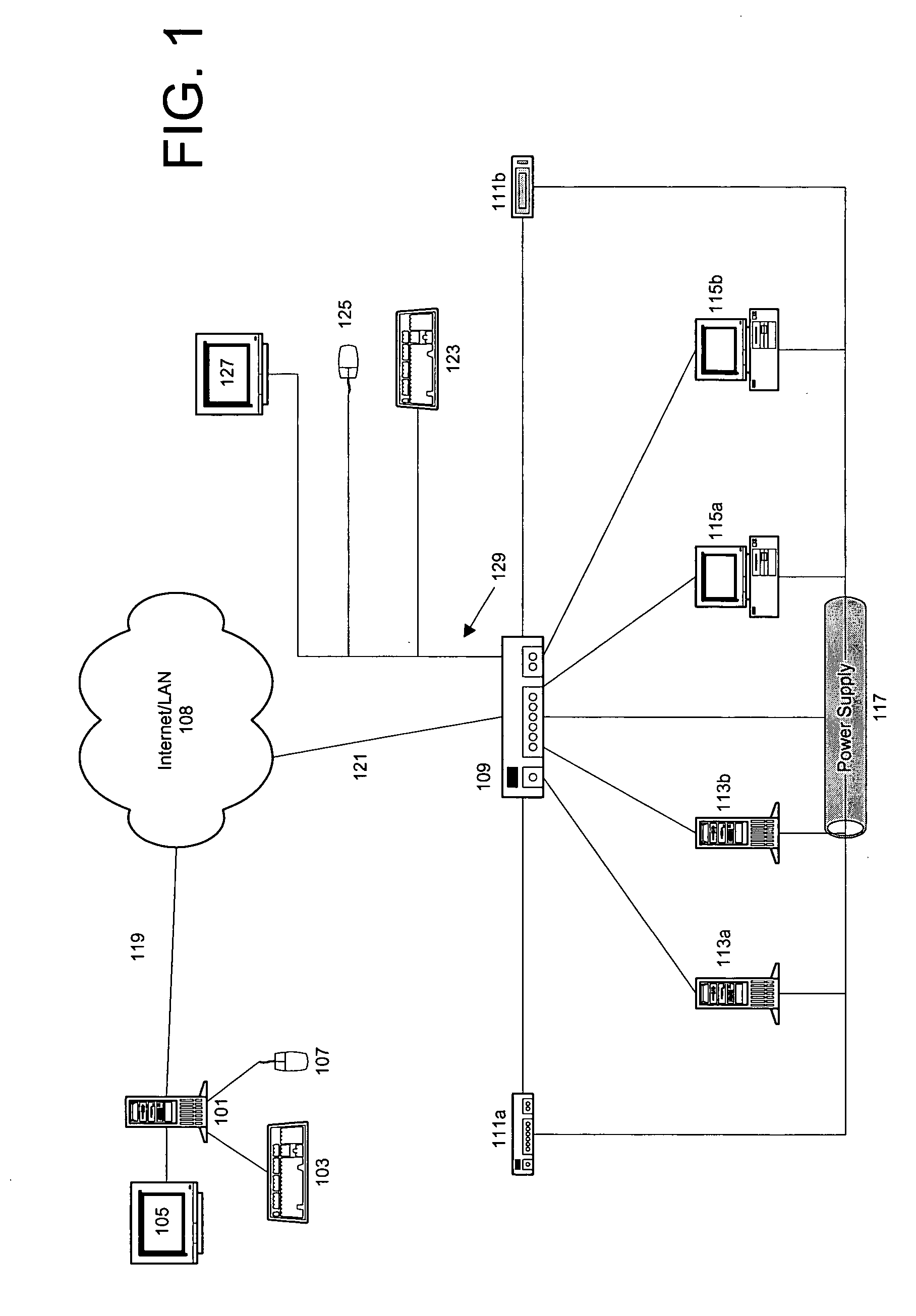
[0091] Referring first to FIG. 1, depicted is the architecture of the preferred embodiment of a remote network management system in accordance with the present invention. Specifically, a remote network management system is shown includi...


PUM


Abstract

The present invention discloses a remote network management system for coupling a series of remote serial devices, servers, and computers to one or more user workstations allowing for selective access of the remote devices. The remote serial devices, servers, and computers are all connected to a remote management unit which interfaces the user workstations to the remote devices. The power supply of each remote device is also connected to the remote management unit through a controllable power supply. The video from the remote networking equipment is digitized and optimized by an LCD controller located within the remote management unit before it is compressed for transmission. An option menu containing a menu of all the remote devices allows a user to select and operate any of the remote devices. The option menu is also utilizes to selectively control the power to the remote serial devices, servers, and computers.

Description

FIELD OF THE INVENTION [0001] The present invention relates generally to a system for video digitization and image correction. Specifically, the improved video digitization system of the present invention utilizes an LCD controller to digitize the video from a remote computer for transmission via a KVM switch to a user workstation. The LCD controller also performs the functions of video mode detection, auto-adjustment for sampling phase and frequency, picture alignment, color alignment, color adjustment, upscaling / downscaling, and image position. BACKGROUND OF THE INVENTION [0002] In a typical computer environment, a Local Area Network (“LAN”) allows for one or more computer servers to be connected to several computers such that the resources of each server are available to each of the connected computers. The LAN is typically comprised of networking equipment such as routers, hubs, switches, etc. In such a configuration, a dedicated keyboard, video monitor and mouse may be employed...

Claims


Application Information

Patent Timeline
IPC IPC(8): G16H30/40H04NH04N7/16H04N7/173H04N7/18H04N19/89
CPCG06F19/321H04N7/17336H04N7/165G09G2370/24G16H30/40
Inventor HOERL, DAVID
Owner RIIP
Why Eureka
Try Eureka