Paint particle deflector

a technology of deflector and paint, which is applied in the direction of breathing protection, protective clothing, hats, etc., can solve the problems of light impairing particles and fluids, and achieve the effect of improving the safety of workers and cost-effectiveness

a technology of deflector and paint, which is applied in the direction of breathing protection, protective clothing, hats, etc., can solve the problems of light impairing particles and fluids, and achieve the effect of improving the safety of workers and cost-effectiveness

US20050114986A1Inactive Publication Date: 2005-06-02HOBART JAMES MICHAEL

Image

  • Paint particle deflector
  • Paint particle deflector
  • Paint particle deflector

Examples


Embodiment Construction

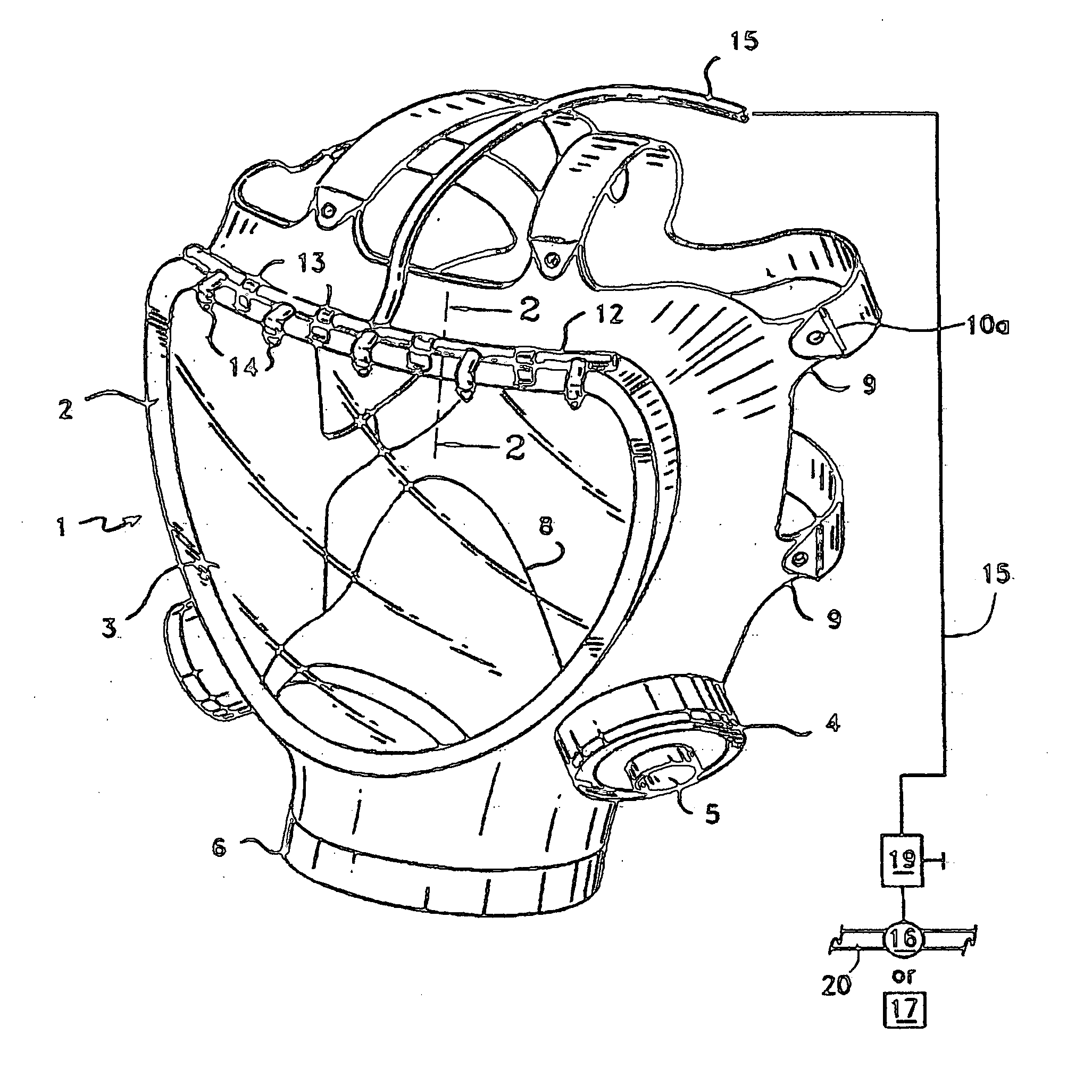
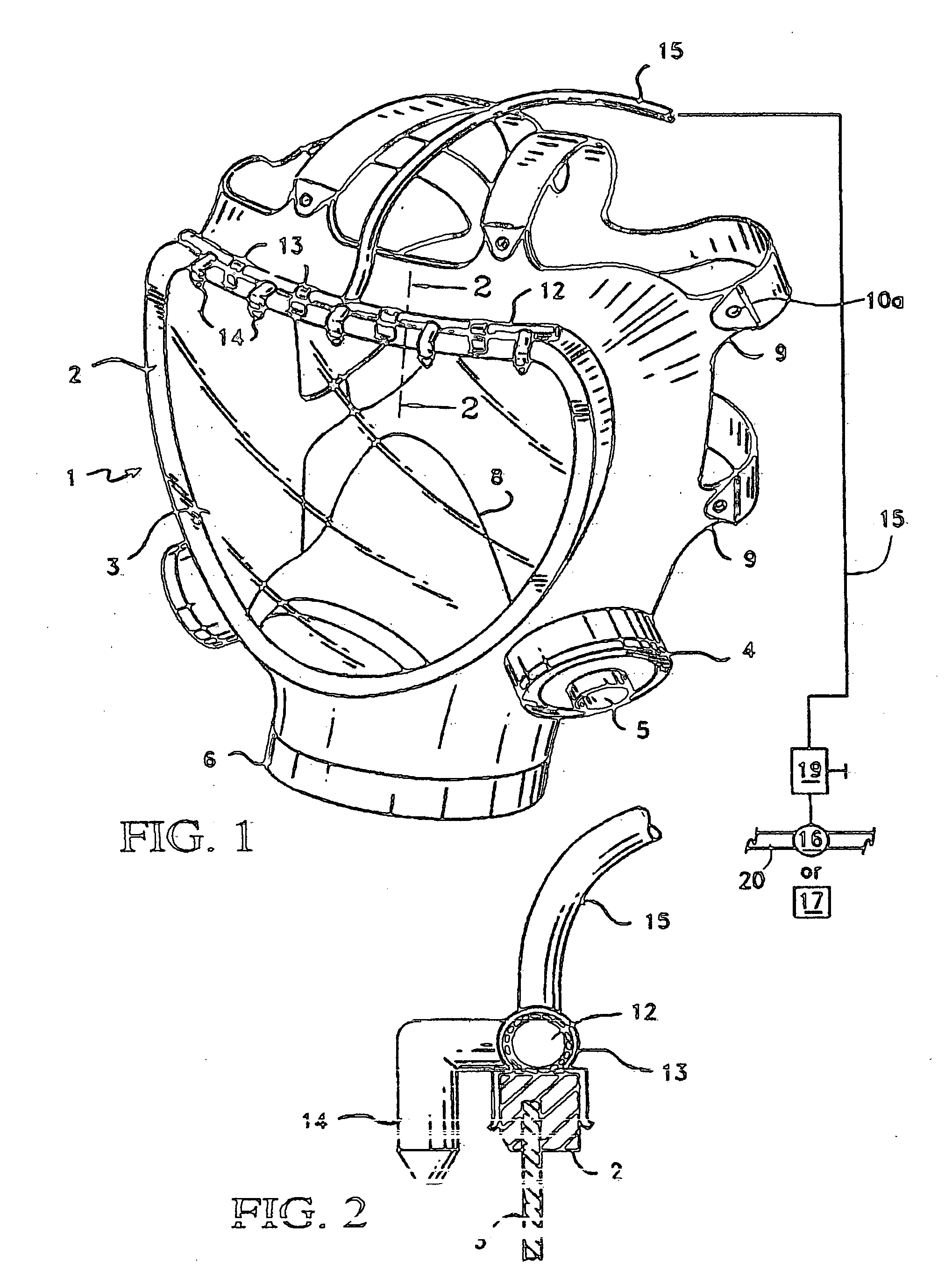
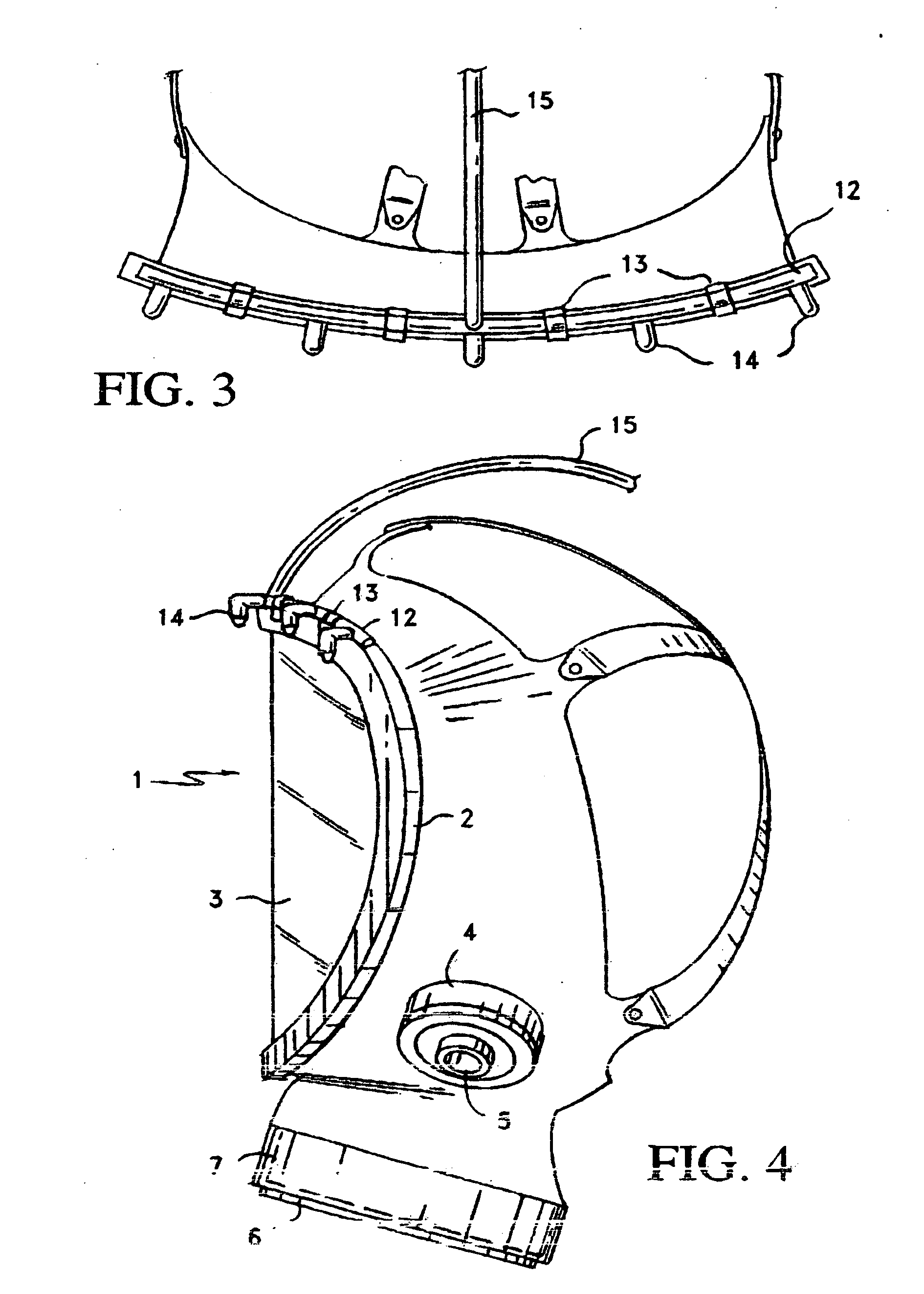
[0022]FIG. 1 shows a rubber frame that constitutes a shielding mask 1 having a gasket 2. Adhesively fitterd within the gasket is a concave lens or glass shield 3. At the sides near the lower end of the mask adjacent the gasket are two cylindrical projections 4 that contain an air inlets 5. Between the two outlets and front and center is a larger cylindrical projection 6 that is enclosed by a filter 7 for receiving incoming air. The filter projects inwardly and a nose piece 8 is attached around the thinner edge of the cylinder. Integral with an inner edge of the gasket are 6 tabs 9 to which an equal number of adjustable straps 10 are secured by a conventional snap button 10a. There are two straps on each upper and lower side and two straps extend from the top. All the straps intersect at a somewhat hexagonically shaped piece 11 located about the mid region in the back of the head. The straps secure the mask to the head. A ¼″ copper tube 12 is fastened in an arc with spring clips 13 a...


PUM


Abstract

A painter's mask has an aperture in which is inserted a glass or lens protective shield. The shield has a gasket having an upper edge on which is attached a header arranged in an arc. Projecting from the arc are a number of spaced atomizers which deliver jets of pressurized air over and in front of the shield to deflect falling paint particles and liquid from the shield during a paining operation.

Description

[0001] The first application claimed priority based on provisional application 60 / 281,719 filed on Apr. 6, 2001; however, this priority has become null nd void because of the following circumstances. This application was assigned an application Ser. No. of 10 / 115,926, a filing date of Apr. 5, 2002 and an Art Unit of 3765. The Attorney inadvertently overlooked a requirement that Substitute Drawings were required under 37 CFR 1.84 and a two month period for resaponse from the date of the notice May 15, 2002. The Attorney only discovered the error by chance. He inquired from Art Unit 3765 about a month ago why he was not getting any response to the patent application, and as explained above, he discovered the facts. Accordingly, while he never did get an official Notice of Abandonment of application Ser. No. 10 / 115,926, he presume it to be so. Therefore the present application cannot be considered a Continuation application of application Ser. No. 10 / 115,926.[0002] This invention is di...

Claims


Application Information

Patent Timeline
02 Jun 2005
Publication
US20050114986A1
IPC
A42B3/26; A62B18/00
CPC
A62B18/003; A42B3/26; A41D13/1184
Inventors
HOBART, JAMES MICHAEL