Coupling and decoupling assembly of pipe having double valve

a technology of spherical shape valve and pipe, which is applied in the direction of couplings, mechanical devices, transportation and packaging, etc., can solve the problems of pipe corrosion, cracking or breaking, air pollution, etc., and achieve the effects of preventing air pollution, wasting resources, and a disastrous acciden

Inactive Publication Date: 2008-01-03
KOREA ATOMIC ENERGY RES INST +1
View PDF16 Cites 9 Cited by
  • Summary
  • Abstract
  • Description
  • Claims
  • Application Information

AI Technical Summary

Benefits of technology

[0012]An aspect of the present invention provides a coupling / decoupling assembly of a pipe which can prevent air pollution, a disastrous accident, and waste of resources, without eliminating a fluid in the pipe, since valves are coupled with ends of two pipes.

Problems solved by technology

The pipes may corrode from being used for an extended period of time, and may have a crack or may be broken due to an external impact or a sudden state change of a fluid which flows through inside the pipes.
Conventionally, it has been a problem that the fluid which flows through the pipe is leaked to an outside to cause air pollution and waste of resources when the pipe is repaired or replaced.
In the conventional method, it takes a great amount of time to replace and repair the pipe, and waste of resources and air pollution may occur when the fluid is leaked out.
As an example, when a great amount of oil and liquefied petroleum gas (LPG), which are shipped or stored in a huge vessel or in a huge storage base, are transferred to another vessel or base, the oil and LPG may be leaked out.
These operations are complex, and a working speed may be lowered due to the complex operation.
Also, when the fluid is a hot fluid, a burn may occur due to the hot fluid, and when the fluid is a radioactive material, radiation exposure may occur.
Also, a container is required to contain the eliminated fluid, and air pollution may occur when disposing of the fluid.

Method used


Image

  • Coupling and decoupling assembly of pipe having double valve
  • Coupling and decoupling assembly of pipe having double valve
  • Coupling and decoupling assembly of pipe having double valve

Examples


Embodiment Construction

[0041]Reference will now be made in detail to exemplary embodiments of the present invention, examples of which are illustrated in the accompanying drawings, wherein like reference numerals refer to the like elements throughout. Exemplary embodiments are described below to explain the present invention by referring to the figures.

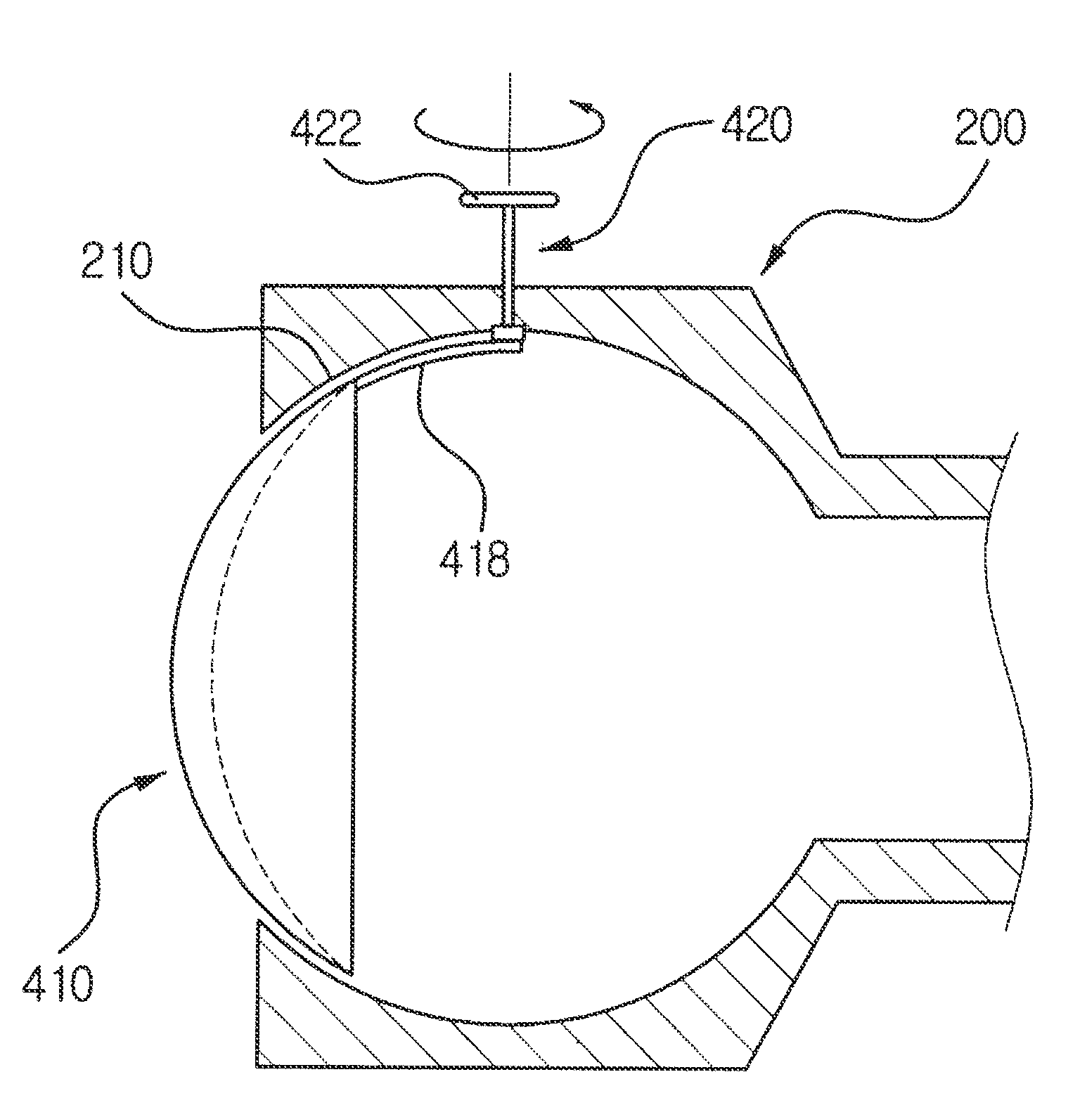
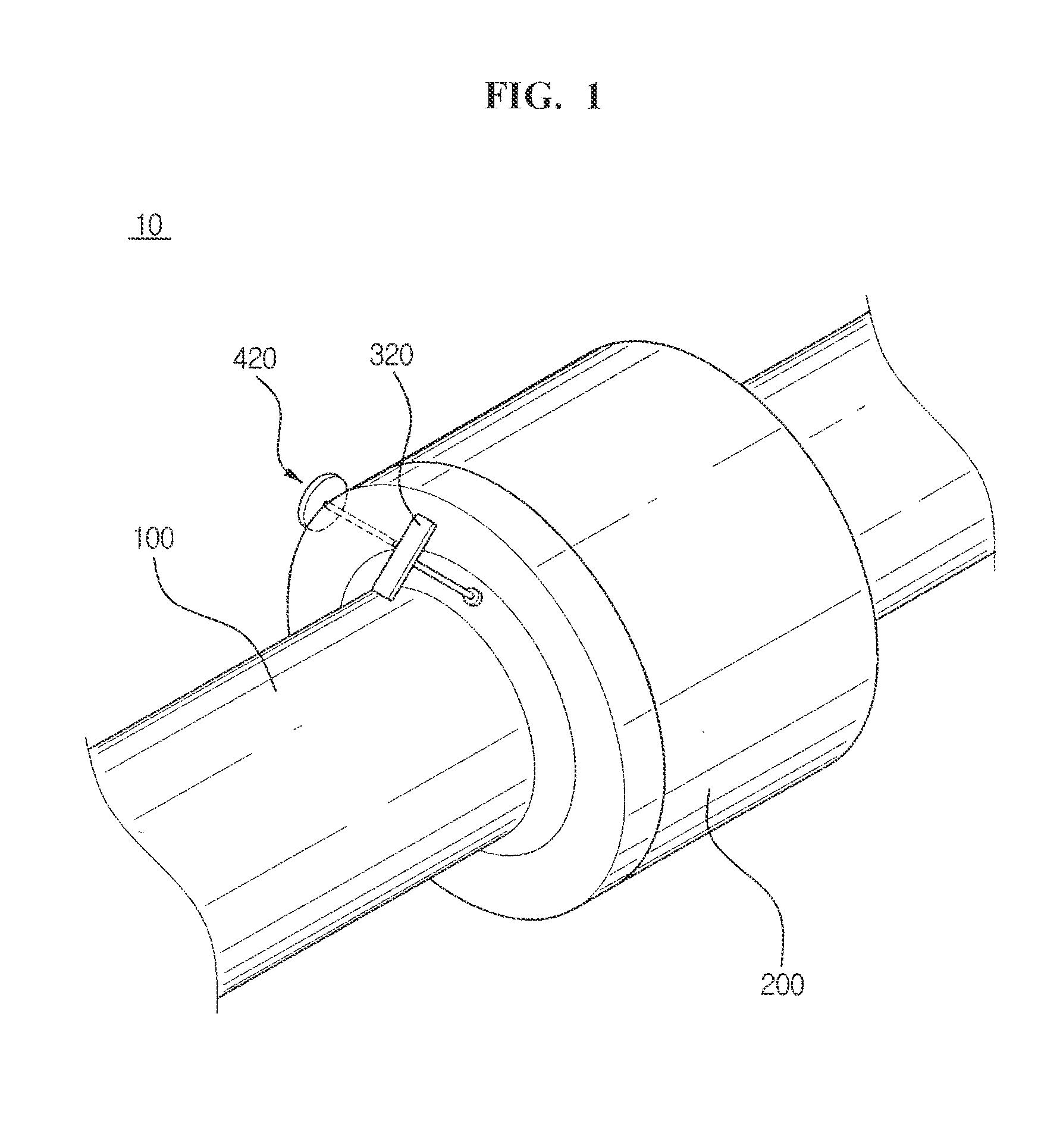
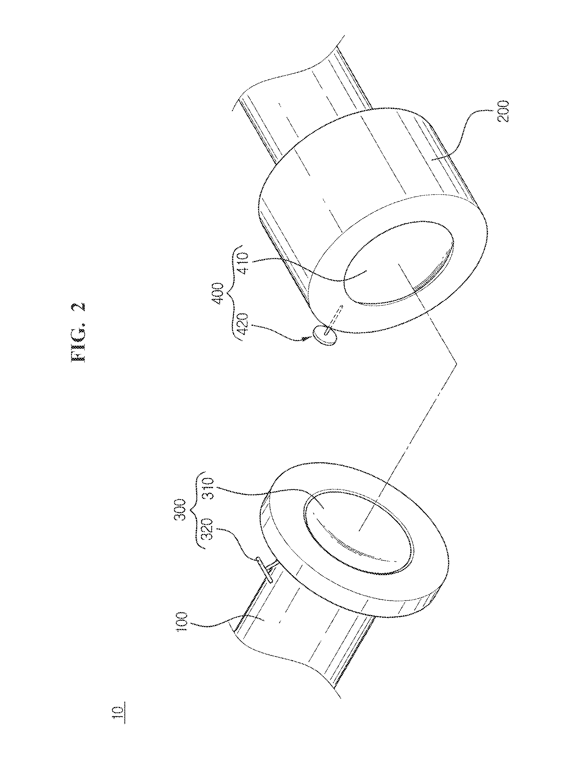
[0042]FIG. 1 is a perspective view illustrating a coupling / decoupling assembly 10 of a pipe according to an exemplary embodiment of the present invention, and FIG. 2 is a perspective view illustrating a separated coupling / decoupling assembly 10 according to an exemplary embodiment of the present invention.

[0043]As illustrated in FIGS. 2 through 4, the coupling / decoupling assembly 10 includes a first pipe 100 and a second pipe 200, the second pipe 200 being coupled / decoupled with the first pipe 100. Also, the coupling / decoupling assembly 10 includes a first valve unit 300 being joined with the first pipe 100 and a second valve unit 400, the first valve unit ...


PUM


Abstract

A coupling/decoupling assembly of a pipe which can selectively open/close a flow channel of the pipe is provided. In the coupling/decoupling assembly of the pipe, a first valve and a second valve are respectively joined with each end of a first pipe and a second pipe. A first driving axis and a second driving axis are respectively joined with each end of the first valve and the second valve. An outer surface and an inner surface of the first and second valves are formed in a spherical body, and the inner surface of the first valve and the outer surface of the second valve are overlapped with each other to close the flow channel of the pipe, and the inner surface of the first valve and the outer surface of the second valve having an identical radius of a curvature.

Description

CROSS REFERENCE TO RELATED APPLICATION[0001]This application claims the benefit of Korean Patent Application No. 10-2006-0051128, filed on Jun. 7, 2006, in the Korean Intellectual Property Office, the disclosure of which is incorporated herein by reference.BACKGROUND OF THE INVENTION[0002]1. Field of the Invention[0003]The present invention relates to a coupling / decoupling assembly of a pipe using a spherical shape valve, and more particularly, to a coupling / decoupling assembly of a pipe which can selectively prevent a flow channel when coupling / decoupling the pipe by a valve having a part of a spherical body inside the pipe.[0004]2. Description of Related Art[0005]Pipes in various sizes and types are coupled in all facilities and machine apparatuses, from large-scale industrial facilities such as power plants and petrochemical plants to air conditioners and refrigerators in offices and homes. The pipe transfers various types of fluids such as water, vapor, a refrigerant, and the li...

Claims


Application Information

Patent Timeline
Patent Type & Authority Applications(United States)
IPC IPC(8): F16L55/00
CPCF16L55/1018F16K1/225F16K1/223F16K1/222F16K1/221Y10T137/87933Y10T137/87973F16L37/28F16L37/30
Inventor CHANG, SEOK KYUMOON, SANG KICHO, SEOKKIM, BOK DEUK
Owner KOREA ATOMIC ENERGY RES INST
Why Eureka
Try Eureka