Corner key for connecting profiles together and frame work assembly

a technology for connecting profiles and frame work, which is applied in the direction of corners/edge joints, doors/windows, and building roofs, etc., can solve the problems of assembly requirements, large working area, and high cost of cutting equipment, and achieves high production efficiency and high production efficiency

Inactive Publication Date: 2005-06-02
FENEGLOBE SYST
View PDF28 Cites 35 Cited by
  • Summary
  • Abstract
  • Description
  • Claims
  • Application Information

AI Technical Summary

Benefits of technology

[0021] It is an object of the present invention to provide a corner key and a frame work assembly that can overcome the prior art deficiencies and shortcomings.
[0022] It is another object of the present invention to provide a corner key for connecting two or more profiles together and forming a frame work assembly in a simple, yet reliable manner with a minimal effort and low manufacturing costs.
[0042] The invention as well as its numerous advantages will be better understood by reading of the following non-restrictive description of a preferred embodiment made in reference to the appending drawings.

Problems solved by technology

A disadvantage of producing mitre joints is that they require relatively expensive cutting equipment to make them.
Such equipment also requires a larger working area and also more highly skilled labour.
However, these assemblies require very complex machining preparation.
However, perpendicular fastener insertion through thermoplastic (PVC) profiles is not satisfactory because of the low tear resistance of such materials.
This technique is disadvantageous in that the frame profiles are to be secured to the corner key in two steps, thus increasing manufacturing time.
None of the above mentioned documents address the problem of the possibility of water and air leakage through the joints between the profiles and the corner keys, nor any description of preventive measures to preclude such leakages.
The preparation of such openings requires special equipment and affords extra labour.

Method used


Image

  • Corner key for connecting profiles together and frame work assembly
  • Corner key for connecting profiles together and frame work assembly
  • Corner key for connecting profiles together and frame work assembly

Examples


Embodiment Construction

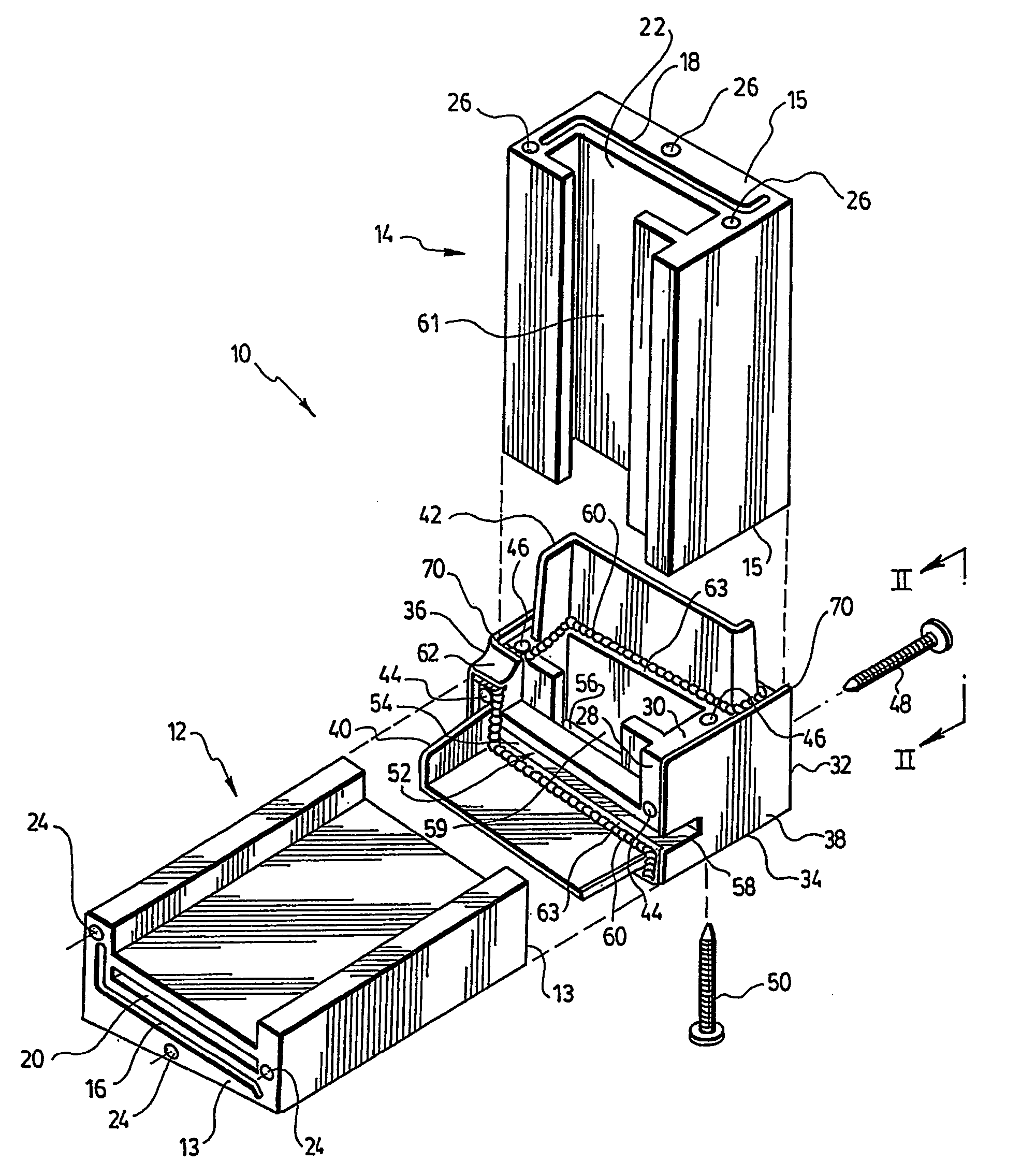
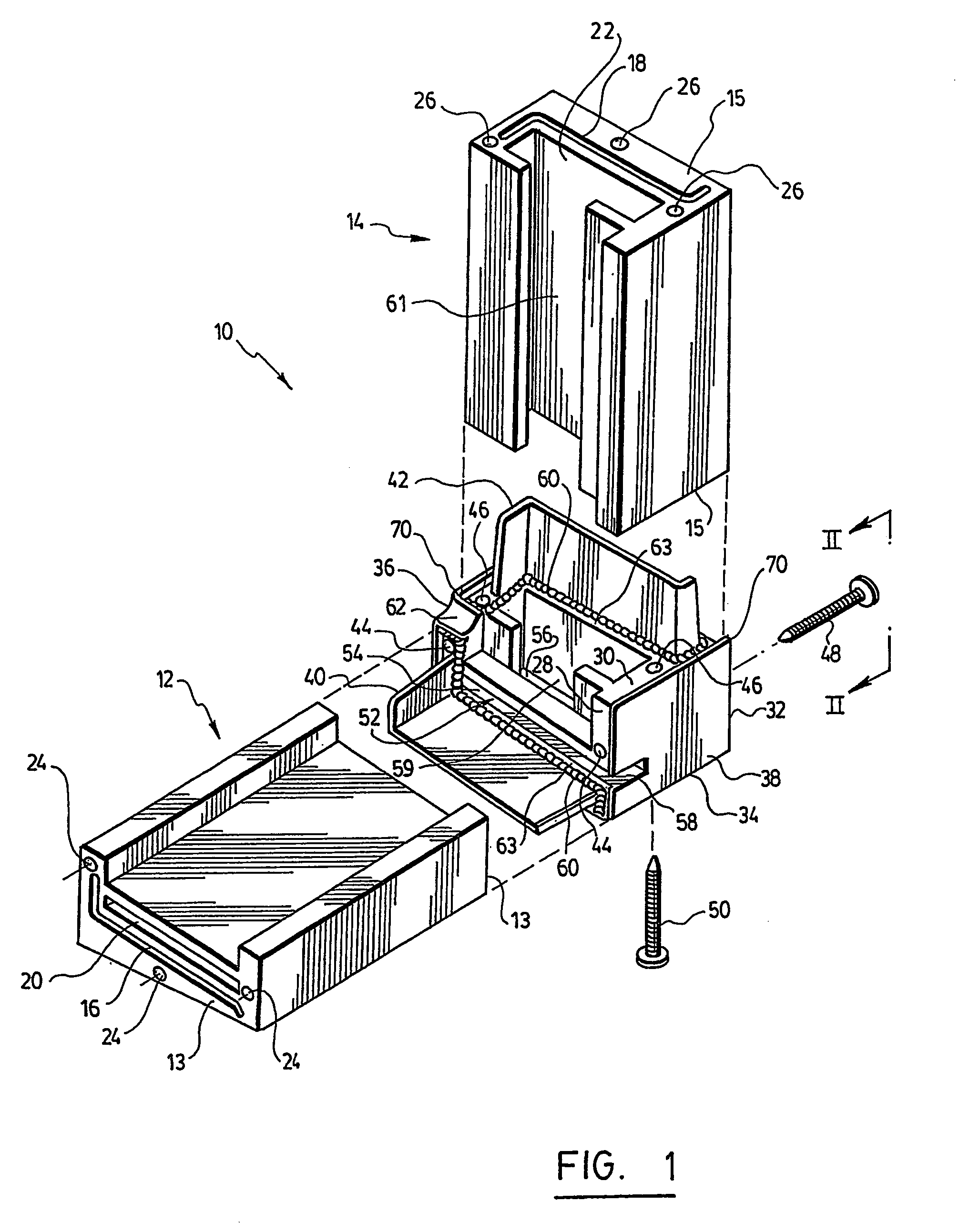
[0050] Referring to FIG. 1, there is shown a corner key 10 according to a preferred embodiment of the present invention. Also shown are portions of two profiles, one corresponding to a sill 12 and the other to a jamb 14 that are to be connected together by means of the corner key 10 to form part of a window frame assembly.

[0051] Those skilled in the art will understand that although only two window frame profiles 12, 14 are illustrated, the teachings according to the present invention are also applicable to any number of profiles or to any other general purpose profiles that are to be jointed with a corner key. In particular, it will be understood that the present teachings apply not only to window frames, but also to door frames, and to other similar structural assemblies as well.

[0052] The corner key 10 that is illustrated is preferably used as a right side lower corner key, but those skilled in the art will also understand that this corner key 10 can be modified so that it can ...


PUM


Abstract

A corner key (10) for connecting profiles (12, 14) together and a frame work assembly formed of such corner keys (10) and (profiles (12, 14). Each profile (12, 14) has an anchoring channel (16, 18), a drainage and venting passage (20, 22) and a securing bore (24, 26). The corner key (10) has two adjacent inner corner faces (28, 30), two adjacent outer corner faces (32, 34), and opposite inner and outer side corner faces (36, 38). Tabs (40, 42) on the inner corner faces (28, 30) guide the coupling of the profiles (12, 14). Fasteners (48, 50) are inserted through the outer corner faces (32, 34) in corner key bores (44, 46) and in the bores (24, 26) of the profiles (12, 14). A drainage and venting passage (52) in the corner key (10) communicates with the drainage and venting passages (20, 22) of the profiles (12, 14).

Description

FIELD OF THE INVENTION [0001] The present invention relates to a corner key for connecting profiles together and also to a frame work assembly that includes such corner keys and profiles. BACKGROUND OF THE INVENTION [0002] Corner keys and lineal profiles are well known in the art, particularly in the context of windows and doors. A lineal profile in this context designates either a sash profile or a frame profile. A corner key is used to connect the sash or frame profiles together. [0003] As it is known in the art, a sash element in the context of windows forms the mobile and working portion of a window. The sash element forms a perimeter called a sash frame that holds the necessary working hardware to allow the sash to slide, pivot, tilt, lock, etc. The sash element also includes the assembly of glazing and the edge-surrounding sash profiles. Sash profiles include top and bottom horizontal rails, and vertical stiles. A sash in the context of doors is most commonly referred to as a ...

Claims


Application Information

Patent Timeline
Patent Type & Authority Applications(United States)
IPC IPC(8): E06B3/96E06B3/964
CPCE06B3/9616E06B3/9641E06B3/9636
Inventor SCHMIDT, HELMUT
Owner FENEGLOBE SYST
Why Eureka
Try Eureka