Master cylinder

a technology of master cylinder and cylinder body, which is applied in the direction of rotary clutches, braking systems, fluid couplings, etc., can solve the problems of deteriorating the feel of the driver's brake pedal, low strength of the primary cup, and impede the stable seating of the primary cup

Active Publication Date: 2005-06-02
ADVICS CO LTD
View PDF6 Cites 25 Cited by
  • Summary
  • Abstract
  • Description
  • Claims
  • Application Information

AI Technical Summary

Benefits of technology

[0028] Without the fluid passage defined between the rear surface of primary cup and the rear end wall of the cup-receiving groove by the protrusions or the groove or grooves formed on the rear surface of the cup, a closed space may develop in the cup-receiving space at its radially outer corner, and brake fluid sealed therein may impede stable seating of the primary cup. Also, a negative pressure produced in the pressure chamber may cause a portion of the primary cup to get stuck on the wall of the cup-receiving groove. The fluid passage defined by the protrusions or the grooves formed on the rear surface of the cup prevents formation of such a closed space.

Problems solved by technology

One disadvantage of the master cylinder of Publication 1 is that the lip of the primary cup, which extends forwardly from its base portion, is low in strength.
This deteriorates the driver's brake pedal feel.
This of course complicates the structure, increases the number of assembling steps and pushes up the cost.
This arrangement also complicates the structure of the master cylinder.

Method used


Image

  • Master cylinder
  • Master cylinder
  • Master cylinder

Examples


Embodiment Construction

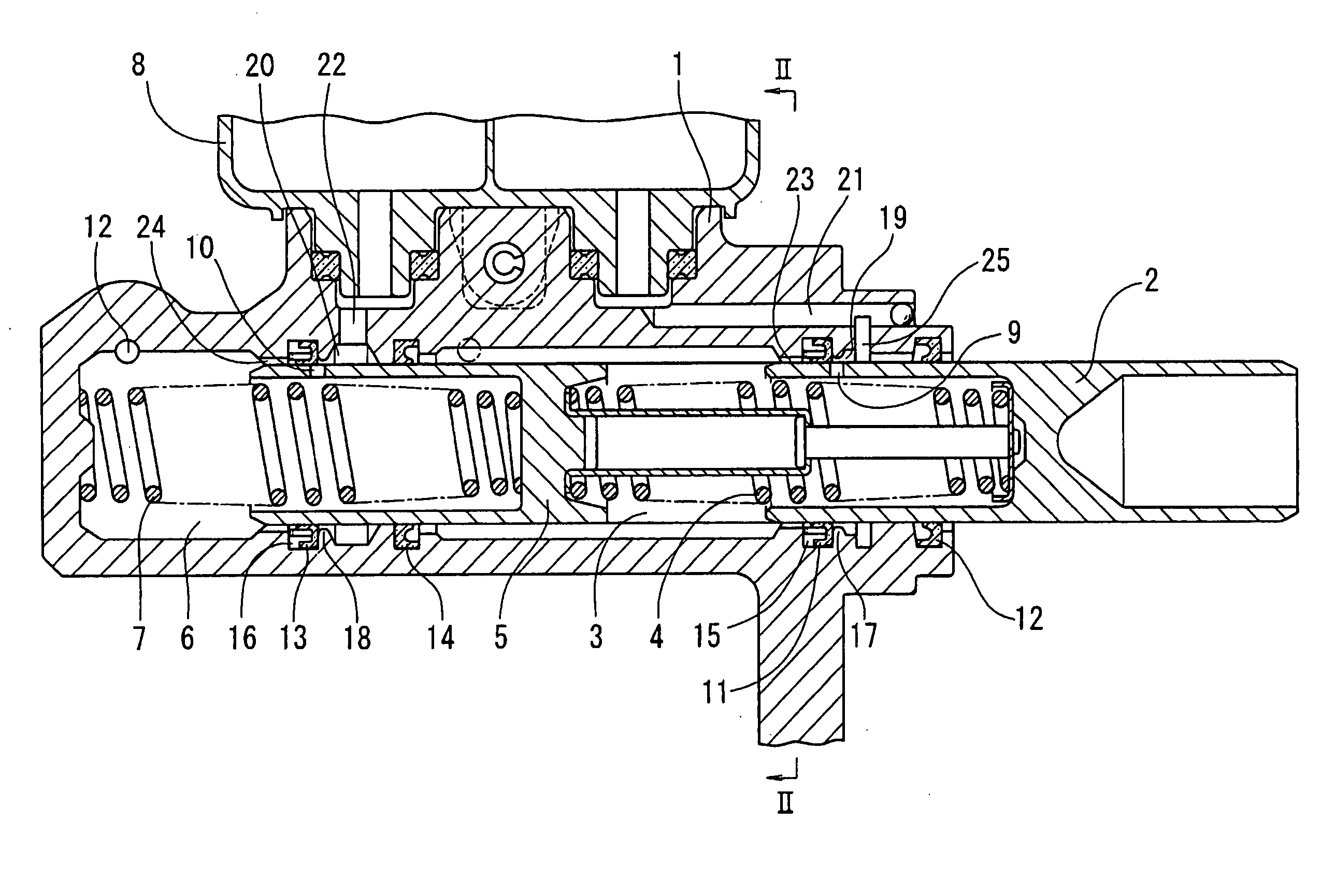
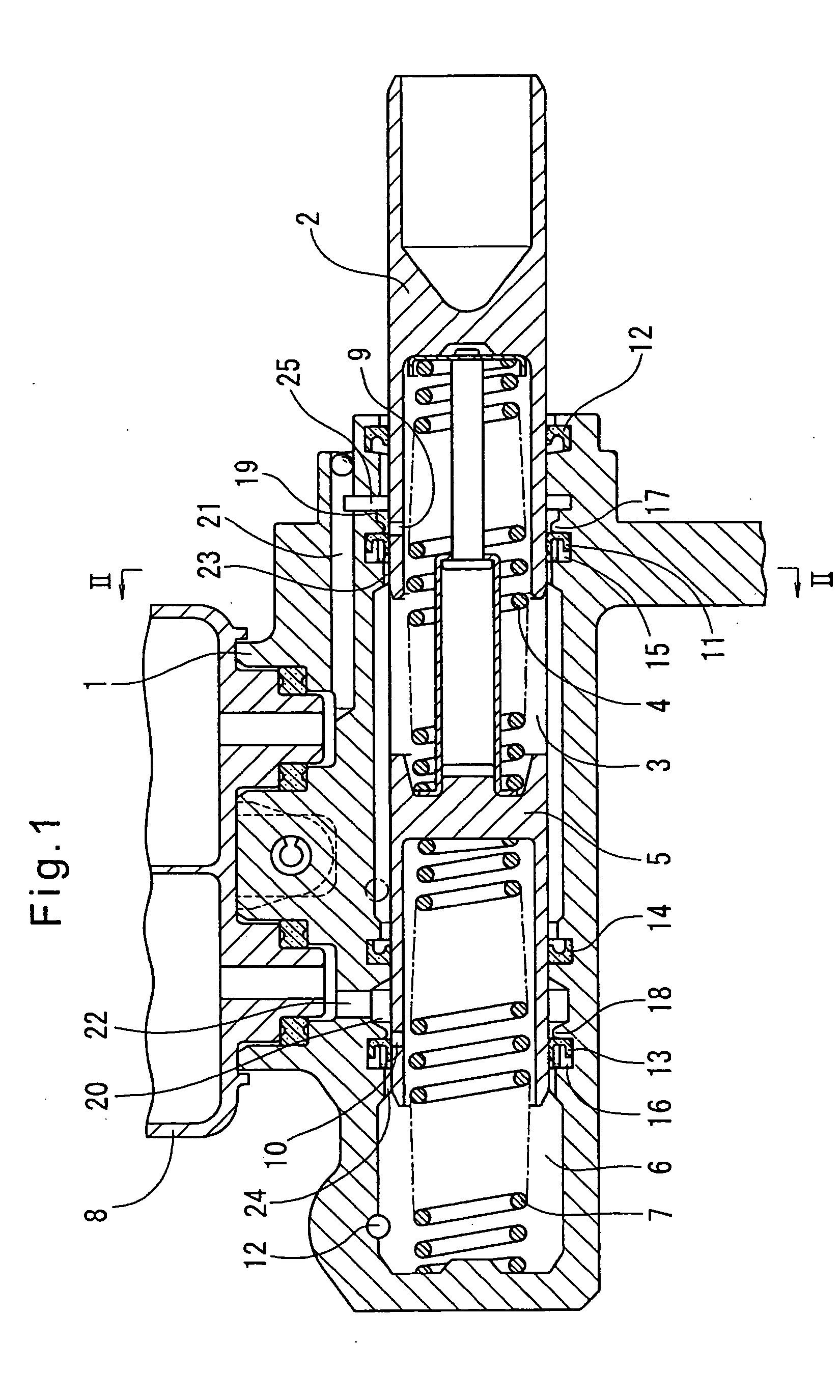
[0040] Now referring to the drawings, FIG. 1 shows the entire master cylinder embodying the present invention. It comprises a cylinder body 1, a primary piston 2 slidably received in the cylinder body 1, a secondary piston 5 slidably received in the cylinder body 1 in front (leftwardly in FIG. 1) of the primary piston 2. A first pressure chamber 3 is defined in the cylinder body 1 between the primary and secondary pistons 2 and 5. A second pressure chamber 6 is defined in the cylinder body 1 between the secondary piston 5 and the front (left-hand) end wall of the cylinder body. The primary piston 2 pressurizes brake fluid in the first pressure chamber 3 to generate brake hydraulic pressure therein. The secondary piston 5 pressurizes brake fluid in the second pressure chamber 6 to generate brake hydraulic pressure therein. Return springs 4 and 7 for the primary and secondary pistons 2 and 5 are mounted in the first and second pressure chambers 3 and 6, respectively.

[0041] The primar...


PUM


Abstract

A master cylinder includes a primary cup received in a groove formed in the inner wall of the cylinder body. Projections are formed on a radially inner portion of the cup so as to protrude forwardly from the front end of the radially inner portion. The projections are adapted to be pressed against the front end wall of the cup-receiving groove and elastically deformed under a pressure difference produced between the front and rear ends of the cup when the piston is returned quickly, allowing the cup to advance in the cup-receiving groove. When the cup advances in the groove, a fluid passage is defined between a base portion of the cup and the rear end wall of the groove. Brake fluid from the reservoir flows through this fluid passage, through a gap formed between a radially outer portion of the cup and the radially outer wall of the groove when the radially outer portion of the cup is deformed by the fluid flow, and through a fluid passage defined between the cup and the front end wall of the groove by the projections.

Description

BACKGROUND OF THE INVENTION [0001] This invention relates to a master cylinder used in a vehicle hydraulic brake system, and particularly a master cylinder of the type including a cup received in a groove formed in the inner wall of a cylinder body and a piston for pressurizing brake fluid in a pressure chamber, the piston being in sliding contact with the radially inner periphery of the cup. This type of master cylinder is hereinafter sometimes referred to as a piston-to-cup slide type master cylinder. [0002] Such piston-to-cup slide type master cylinders are disclosed in the following three patent publications: WO-02 / 064410 (Publication 1), JP patent publication 2000-71969 (Publication 2), and U.S. Pat. No. 4,249,381 (Publication 3). [0003] The master cylinder disclosed in Publication 1 includes a primary cup received in a groove formed in the inner wall of the cylinder body for sealing the outer periphery of the piston. The primary cup includes a thick base portion having a lip e...

Claims


Application Information

Patent Timeline
Patent Type & Authority Applications(United States)
IPC IPC(8): B60T11/16B60T11/20B60T11/22B60T11/232B60T11/236
CPCB60T11/22B60T11/236B60T11/232B60T11/16B60T11/20
Inventor TSUBOUCHI, KAORUMITA, KATSUHIROSUZUKI, KOJI
Owner ADVICS CO LTD
Why Eureka
Try Eureka