Structure of heat sink

Inactive Publication Date: 2005-06-02
HSU JUNG YEN
View PDF9 Cites 5 Cited by
  • Summary
  • Abstract
  • Description
  • Claims
  • Application Information

AI Technical Summary

Benefits of technology

[0005] The primary purpose of the present invention is to solve the problems mentioned above and to provide an improved structure of heat sink that relates to heating solution in the liquid state of the closed mini pipeline to evaporate as gas and bring away heat produced when some machine ele

Problems solved by technology

No matter what the structures of heat sink are used habitually menti

Method used


Image

  • Structure of heat sink
  • Structure of heat sink
  • Structure of heat sink

Examples


Embodiment Construction

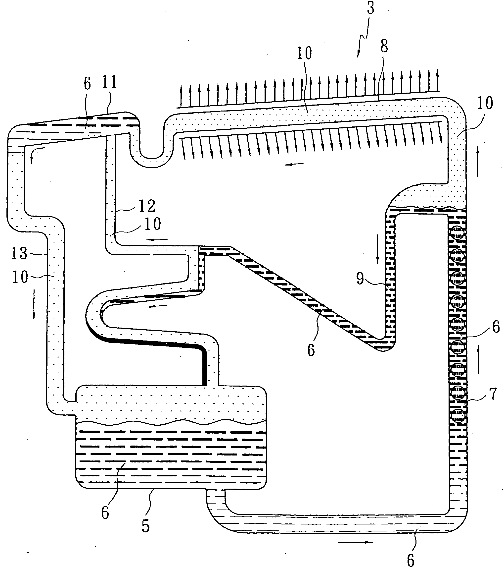
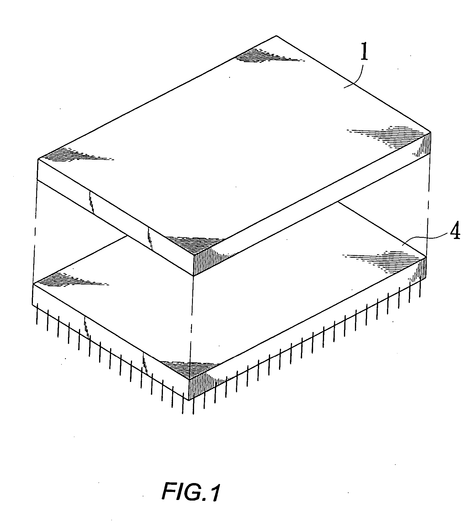
[0008] As showing in FIGS. 1 and 2, an improved structure of heat sink (1) of the present invention is combined with the base (2) and the structure of the closed mini pipeline (3). Within the length and width of the base (2) are in accordance with some machine elements (4) causing waste heat for connecting closely with said machine elements (4) as a whole. By way of the cooling effect produced when the solution in the pipeline of the structure of closed mini pipeline (3) connecting with the base (2) circulate and change mutually in the liquid state and steam, which makes some machine elements (4) in machinery or electronic products running to produce waste heat cooling.

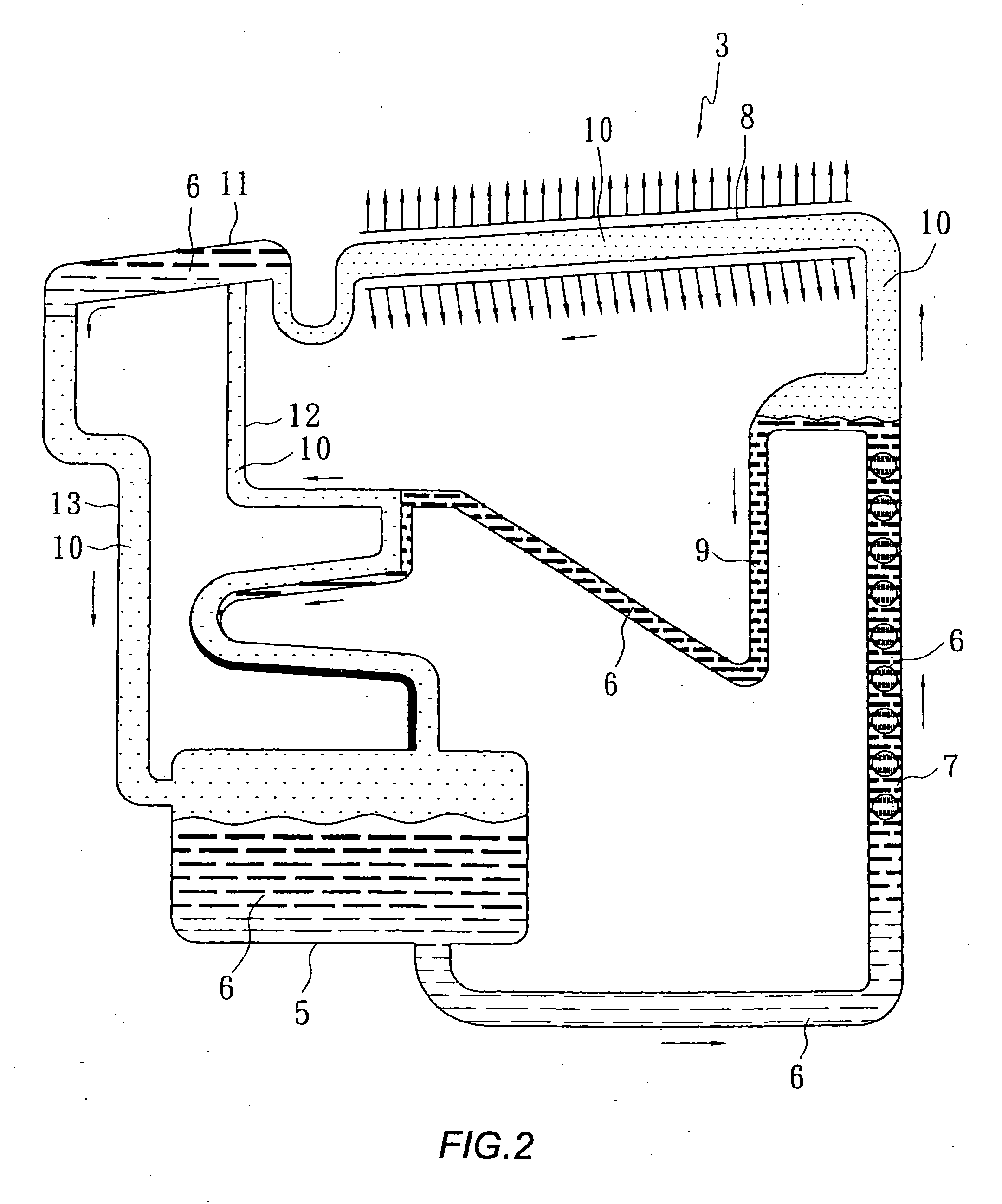
[0009] As showing in FIG. 2, the structure of the closed mini pipeline (3) of the present invention is a circulating network of the closed mini pipeline. Within the liquid tank of concentrated solution (5) contains the mini liquid (6) low the atmosphere pressure is through the generator (7). Liquid in the pipeline is...


PUM


Abstract

An improved structure of heat sink is combined with the base and the structure of closed pipeline. By way of the cooling effect produced when solution in the pipeline of the structure of closed mini pipeline inside the base circulate and change mutually in the liquid state and steam, which makes some machine elements in machinery or electronic products running to cause waste heat cooling.

Description

BACKGROUND OF THE INVENTION [0001] 1. Field of the Invention [0002] The present invention relates to an improved structure of heat sink. Particularly, it relates to an improved structure of heat sink in some machine elements of machinery or electronic products running to cause waste heat. [0003] 2. Prior Art [0004] Look into former heat sink used in some machine elements while machinery or electronic products run to cause waste heat; some of them are made into layer built or multiple needle-pillar type of lead-heat panel by pure aluminum with high heat conduction to contact some machine elements causing waste heat for conducting heat produced as some machine elements cause waste heat. Further, setting an electric fan device in the lead-heat panel to continuously bring heat into ambient air giving off via airflow that avoids to influence the effects of some machine elements when they cause waste heat and make their working temperature too high. No matter what the structures of heat s...

Claims


Application Information

Patent Timeline
IPC IPC(8): F28D15/02H01L23/427
CPCF28D15/0266F28D2021/0029H01L23/427H01L2924/0002H01L2924/00
Inventor HSU, JUNG-YEN
Owner HSU JUNG YEN
Why Eureka
Try Eureka