Lithium ion battery thermal management system and method based on phase change material and mutually embedded fins

A lithium-ion battery and thermal management system technology, applied in the field of battery thermal management, can solve problems such as not being able to meet the multiple thermal demands of lithium-ion batteries, and achieve the effect of improving heat dissipation and slowing down the temperature drop rate

Active Publication Date: 2022-03-29
THE UNIV OF NOTTINGHAM NINGBO CHINA
View PDF5 Cites 0 Cited by
  • Summary
  • Abstract
  • Description
  • Claims
  • Application Information

AI Technical Summary

Problems solved by technology

[0005] Aiming at the defects in the prior art, the present invention provides a lithium-ion battery thermal management system and method based on phase-change materials and inter-embedded fins, which solves the problem that the existing thermal management system based on phase-change materials cannot meet the needs of lithium-ion batteries. Technical issues of multiple heat requirements for batteries under different ambient temperatures or operating conditions

Method used


Image

  • Lithium ion battery thermal management system and method based on phase change material and mutually embedded fins
  • Lithium ion battery thermal management system and method based on phase change material and mutually embedded fins
  • Lithium ion battery thermal management system and method based on phase change material and mutually embedded fins

Examples


Embodiment 1

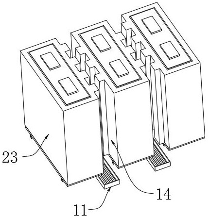
[0052] This embodiment aims to provide one of the better specific implementation structures of the first air intake unit 11 and the first exhaust unit, please refer to image 3 , the first air inlet unit 11 is preferably an air duct, and the air duct communicates with an external cold and heat source. The air duct is provided with a plurality of air outlets, and corresponds to each first heat exchange channel 14 one by one; the first air exhaust The unit is set on the outer wall of the battery box 1; the cold and heat sources can be set away from the battery box 1 to avoid the temperature of the battery box 1 affecting the work of the cold and heat sources; if the battery box is set on an electric car, the air duct can be directly Connected with the car air conditioning system. Specifically, the first air intake unit 11 can blow cold or warm air into the first heat exchange channel 14 as required; It satisfies the heat dissipation and cooling requirements of the battery in hi...

Embodiment 2

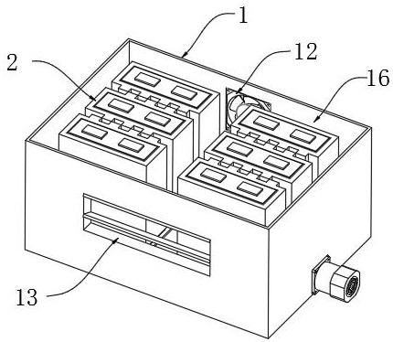
[0054] This embodiment aims to provide one of the better specific implementation structures of the second air intake unit 12 and the second exhaust unit 13. This embodiment can assist Embodiment 1 to obtain better heat dissipation and heat preservation effects, and can be used as Supplementary scheme of embodiment one. see figure 1 The second air intake unit 12 is preferably a heat dissipation fan, and the heat dissipation fan sends the cold air outside the battery box 1 into the second heat exchange channel 15 and / or the third heat exchange channel 16, and can control the air intake rate; The second exhaust unit 13 is preferably an electric louver, which discharges the hot air absorbed in the second heat exchange channel 15 and / or the third heat exchange channel 16, and the electric louver can adjust the opening degree and the air outlet direction. Preferably, a heating wire is provided between the cooling fan and the battery box 1 to blow hot air into the battery box 1 by m...

Embodiment 3

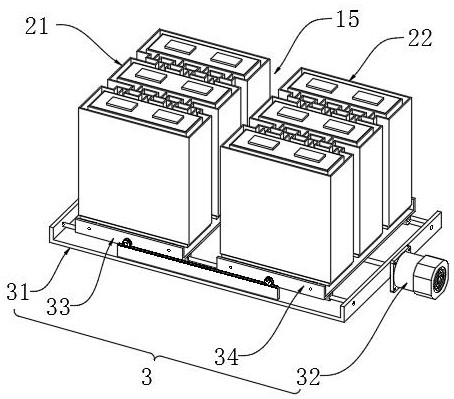
[0056] This embodiment aims to provide one of the preferred specific implementation structures of the driving device 3 . see figure 2 and Figure 5-7 , the driving device 3 includes a base 31, the base 31 is arranged on the inner surface of the bottom of the battery box 1, the base 31 is rotationally connected with the first two-way screw rod 311, and one end of the first two-way screw rod 311 runs through the battery box 1 Afterwards, it is connected to a motor 32 in transmission, and the motor 32 is electrically connected to the controller. Setting the motor 32 outside the battery box 1 can ensure its own heat dissipation, and can also reduce the outline size of the battery box 1 at the same time. Wherein, the two ends of the first two-way screw rod 311 are threadedly connected with the first sliding seat 33 and the second sliding seat 34 respectively, and the first sliding seat 33 and the second sliding seat 34 have the same structure and are respectively slidably connect...


PUM

PropertyMeasurementUnit
melting pointaaaaaaaaaa

Abstract

The invention belongs to the technical field of battery thermal management, and aims to provide a lithium ion battery thermal management system and method based on a phase change material and mutually embedded fins. The thermal management system comprises a battery box, and a lithium ion battery pack and a temperature detection unit are arranged in the battery box; the lithium ion battery pack at least comprises two battery monomers, the peripheries of the battery monomers are coated with a battery inner shell and a battery outer shell, and a phase change material is filled between the battery inner shell and the battery outer shell; a plurality of fins are arranged on the battery outer shell on the opposite sides of the two adjacent battery monomers, the plurality of fins are arranged at intervals, the fins on the opposite sides of the two adjacent battery monomers are arranged in a crossed manner, and a heat-conducting fin is connected between each fin and the battery inner shell; and the driving device is used for driving two adjacent single batteries to move in opposite directions so as to enable the fins on the surfaces of the single batteries to be mutually embedded to realize low-temperature thermal protection, or driving the two adjacent single batteries to move in opposite directions so as to enable the fins on the surfaces of the single batteries to be mutually disembedded to realize high-temperature heat dissipation.

Description

technical field [0001] The invention relates to the technical field of battery heat management, in particular to a lithium-ion battery heat management system and method based on phase change materials and interembedded fins. Background technique [0002] As a new generation of energy conversion technology, lithium-ion batteries have been widely studied and applied in important industrial fields such as new electronic equipment and new energy vehicles. Especially in recent years, the increasing demand for energy consumption has put forward higher requirements on the performance, reliability and life of the currently used lithium-ion batteries. But it should be noted that lithium-ion batteries are very sensitive to their operating temperature and the temperature distribution in the pool. When the operating temperature is too low, the electrochemical reaction rate during the discharge process of the lithium-ion battery will be significantly reduced, and the discharge performan...

Claims


Application Information

Patent Timeline
Patent Type & Authority Applications(China)
IPC IPC(8): H01M10/613H01M10/615H01M10/633H01M10/635H01M10/659H01M10/6556H01M10/6557H01M10/6563
CPCH01M10/613H01M10/615H01M10/633H01M10/635H01M10/659H01M10/6556H01M10/6557H01M10/6563Y02E60/10H01M10/625H01M10/486H01M10/6554H01M10/617H01M2220/20H01M10/6555H01M50/20H01M10/647H01M10/63H01M10/0525H01M10/6551
Inventor 石泳陈冠一叶瀚洋
Owner THE UNIV OF NOTTINGHAM NINGBO CHINA
Why Eureka
Try Eureka