Can

Inactive Publication Date: 2005-06-02
MIZUMA JYUNZI +5
View PDF13 Cites 22 Cited by
  • Summary
  • Abstract
  • Description
  • Claims
  • Application Information

AI Technical Summary

Benefits of technology

[0018] In the above structure, after a pull-ring is lifted and pulled to open a spout by a normal action of opening a can, the pull-ring is rotated around a projection, thereby also rotating an internal sealing member at the same time. Thus, when rotating the internal sealing member up to a position right beneath the spout, the once opened spout can be reclosed. As the internal sealing member seals the spout from an inner side of the top wall, the contents of the can do not spill out if the can drops. In addition, by sealing the spout with the internal sealing member, heat exchange between the inner and outer sides of the can is hindered to control a temperature change of contents of the can. Accordingly, cold contents can be kept c

Problems solved by technology

In addition, by sealing the spout with the internal sealing member, heat exchange between the inner

Method used


Image

  • Can
  • Can
  • Can

Examples


Example

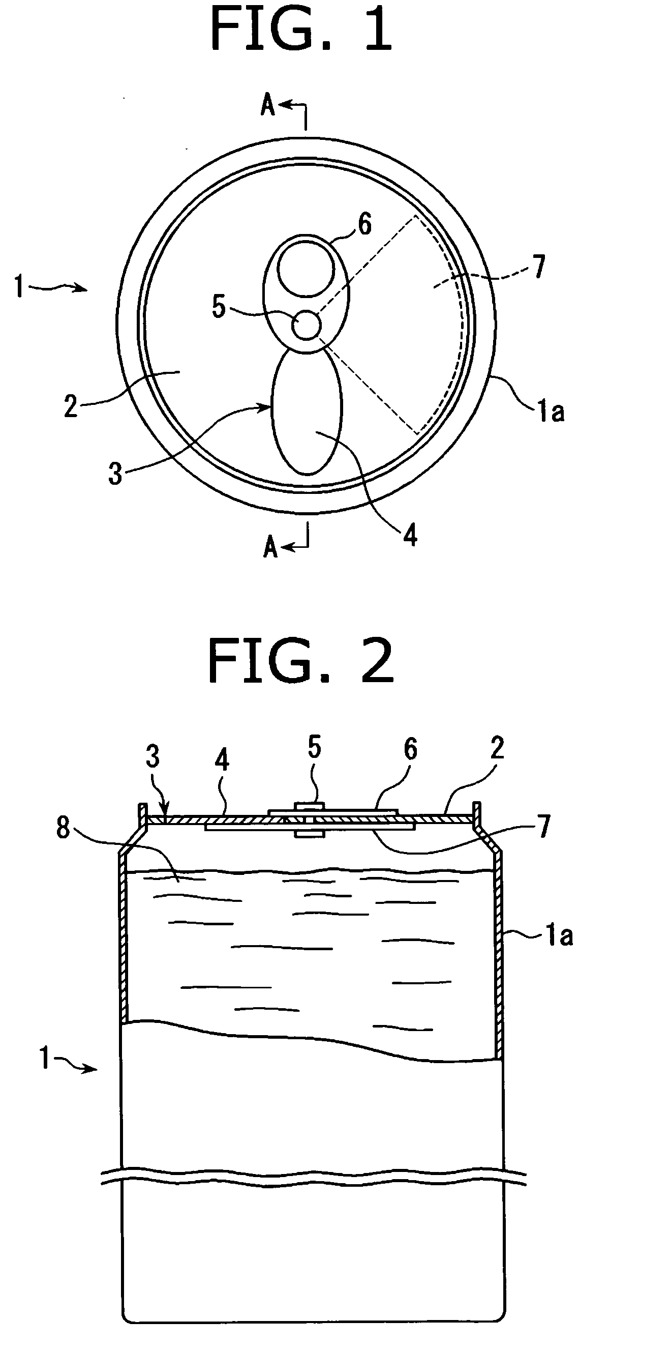
[0033] FIGS. 1 to 4 are drawings showing a first embodiment of the present invention.

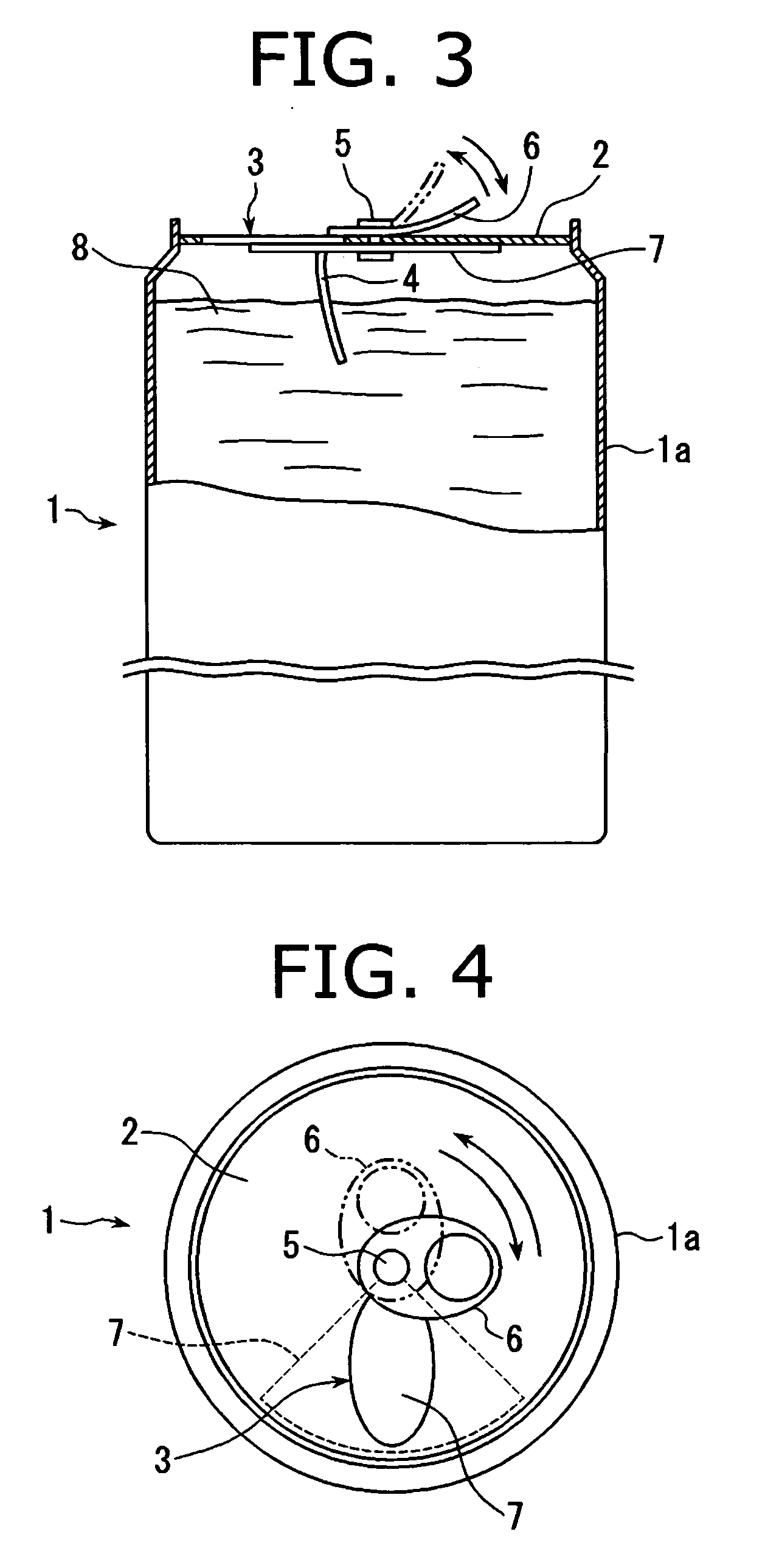
[0034] As shown in FIGS. 1 and 2, a can 1 of this embodiment has a spout 3 which is opened by lifting and pulling a pull-ring 6 fixed on a top wall 2 of a can body 1a with a rivet 5 to bend a sealing tongue portion 4 toward an inside of the can body 1a. On a position inside the top wall 2 and away from the spout 3, an internal sealing member 7 having a size capable of sealing the spout 3 and a fan shape with its pivot mounted to the rivet 5 is disposed in a fixed manner. As an interlocking mechanism to rotate the internal sealing member 7 at the time when the pull-ring 6 is rotated around the rivet 5, provided is a mechanism such that a base end of the pull-ring 6 and the pivot of the internal sealing member 7 are fixed to the rivet 5 on outer and inner sides of the top wall 2, respectively, and, after opening the spout 3, the rivet 5 is rotatably supproted on the top wall 2.

[0035] Referring to FI...

Example

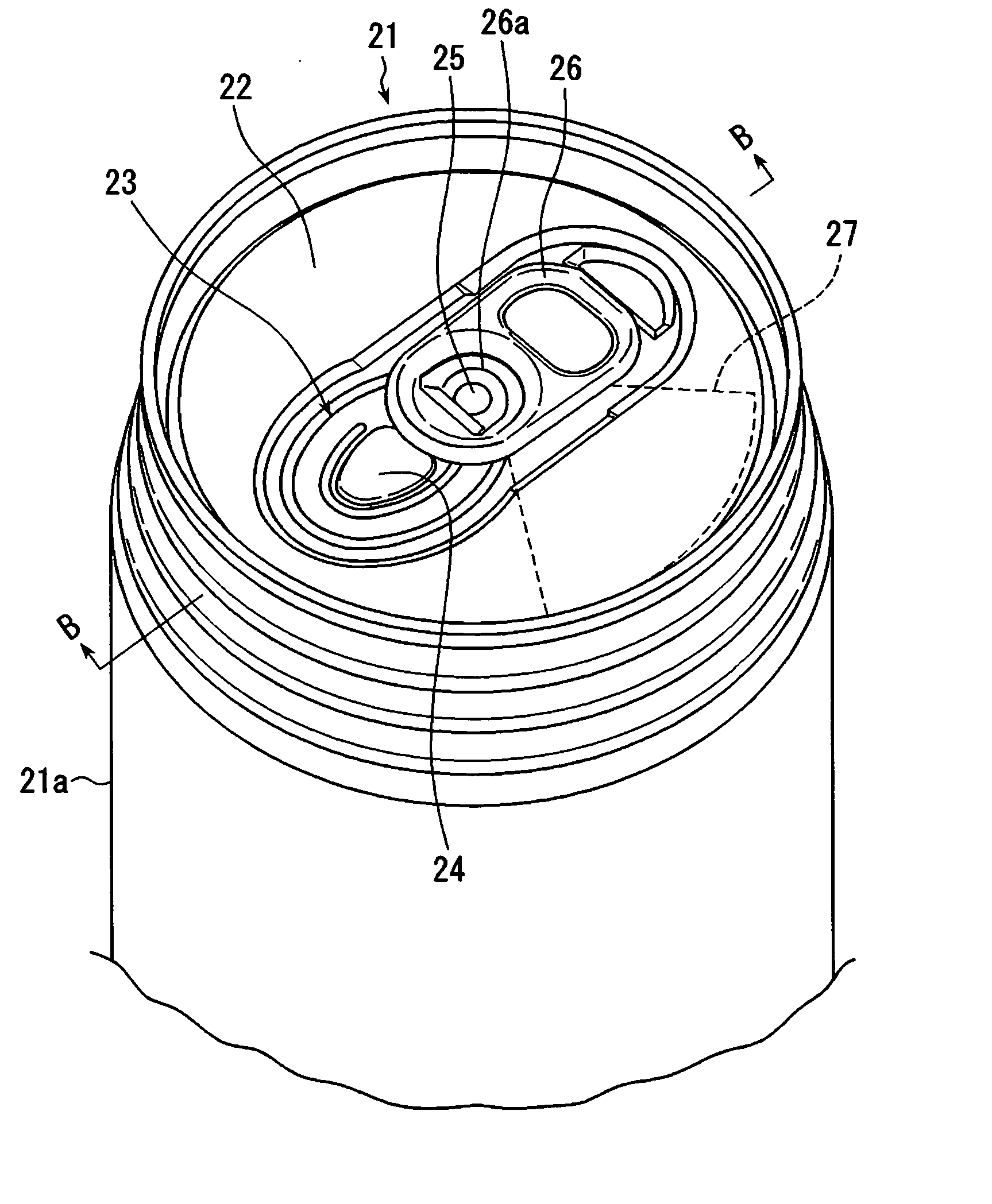
[0042] FIGS. 5 to 13 are drawings showing a second embodiment of the present invention.

[0043] As shown in FIGS. 5 to 8, a can 21 of this embodiment has a spout 23 which is opened by lifting and pulling a pull-ring 26 fixed to a projection 25 formed on substantially a center of a top wall 22 of a can body 21a to bend a sealing tongue portion 24 toward an inside of the can body 21a. On a position inside the top wall 22 and away from the spout 23, an internal sealing member 27 having a size capable of sealing the spout 23 and a fan shape is disposed to be fixed to the projection 25.

[0044] Referring to FIGS. 9 and 10, a structure for fixing the pull-ring 26 and the internal sealing member 27 to the projection 25 will be described below. As shown in FIG. 9, a hat-like pre-pressed projection 25a having an approximately semi lunar form in a plan view is formed at a substantially central position of the top wall 22 before assembly. As shown in FIG. 10, a hat-like projection 27a having an ...


PUM


Abstract

A can (1) of which spout after opening can be securely resealed and can be opened and closed with an easy operation is provided. The can (1) has a spout (3) that is opened by lifting and pulling a pull-ring (6) fixed on a top wall (2) of a can body (1a) with a rivet (5) to bend a sealing tongue portion (4) toward the inside of the can. Inside the top wall (2) and away from the spout (3), an internal sealing member (7) having a fan shape with its pivot mounted to the rivet and a size capable of sealing the spout (3) is disposed to be fixed to the rivet (5). After opening the spout (3), by rotating the pull-ring (6) around the rivet (5), the internal sealing member (7) is also rotated at the same time. As an interlocking mechanism therefor, the rivet (5) is rotatably supported by the top wall (2), and a base end of the pull-ring (6) and the pivot of the internal sealing member (7) are fixed to the rivet (5), respectively.

Description

BACKGROUND OF THE INVENTION [0001] 1. Field of the Invention [0002] The present invention relates to a can with a pull-ring opener, which is used as a container for beverages such as soft drinks, beer and the like. [0003] 2. Description of the Related Art [0004] A can with a pull-ring opener has a spout that can be easily opened by lifting and pulling a pull-ring (or pull top, pull tab) pivotally supported by a rivet on a top wall of the can. Recently, such type of can has been widely used as containers for beverages such as soft drinks, beer and the like. [0005] On the other hand, a spout of a can with a conventional pull-ring opener, once it is opened, is no longer reclosable, which causes inconvenience if the entire contents have not been consumed at once. [0006] In view of the above, cans provided with sealing members that can reclose spouts once opened have been disclosed in some publications such as Unexamined Japanese Utility Model Publication No. 5-7632, Unexamined Japanese ...

Claims


Application Information

Patent Timeline
IPC IPC(8): B65D17/34
CPCB65D17/166Y10S220/906B65D2517/0044B65D2517/0011B65D17/4014
Inventor MIZUMA, JYUNZI
Owner MIZUMA JYUNZI
Why Eureka
Try Eureka