Evaporator door system with movable door

a technology of evaporator doors and movable parts, which is applied in the direction of defrosting, heating types, domestic cooling apparatus, etc., can solve the problems of reducing the effect of defrosting heat exchangers on the area of the cooling system used, and doors may be subject to moisture buildup (condensation), so as to improve the efficiency of defrosting and speed up the defrosting time , the effect of heating exchangers

Inactive Publication Date: 2014-04-22
HASELDINE JR MICHAEL CYRIL
View PDF23 Cites 0 Cited by
  • Summary
  • Abstract
  • Description
  • Claims
  • Application Information

AI Technical Summary

Benefits of technology

[0008]Accordingly, one aspect of the present invention is to allow the sequential defrost of individual evaporators (otherwise know as heat exchangers) while maintaining desired airflow and design temperature in the cooling system. One example of the invention provides movable doors or screens configured to unroll from a stored position to be placed over each evaporator front and / or back side. In one example, the doors are controlled via a PLC and / or frost detection devices. The controller directs the doors to move, for example, downward, into a closed position or upward into an open position. When these doors are closed, i.e., in an unrolled position, the heat exchanger is at least partially isolated from air movement in the remainder of the freezer created by any fans that are often included with cooling systems, especially large-scale cooling systems. Thus, in this example, airflow over the heat exchanger or heat exchangers undergoing defrost is reduced, and the heat exchangers will defrost more efficiently. Another aspect of the present invention is the containment of any heat produced in the defrosting heat exchanger during the defrost process. This containment creates a hot zone around the defrosting heat exchanger, which allows for a faster defrost time than some conventional defrosters. Additionally, the containment of the heat around the defrosting heat exchanger reduces the effect the defrosting heat exchanger on the area of the cooling system used to store items such as food.
[0009]One aspect of the invention uses two doors on each heat exchanger, one on the front side of the heat exchanger and one on the back side of the heat exchanger. In one example, the doors are nylon fabric doors. The doors can be moved to roll or unroll by one or more motors. In an example using one motor, there may be a linkage to actuate the door on one side, typically the back side, of the heat exchanger. Preferably, any doors, shafts, and tracks are compatible with the temperatures normally present in the cooling system. In one example, the doors can be quite wide. In certain embodiments, when the doors are wide, the door preferably includes a reinforcement or “wind rib” in the center of the door to help prevent the door from collapsing due to air movement within the cooling system.
[0010]One beneficial aspect of certain examples of the invention is the reduction in defrost time due to the concentration of heat used to defrost the heat exchangers. Another aspect of the invention is that the door or doors are can be placed in a rolled up (open position) or unrolled (closed position) within a hood, and thus, isolated from the freezer environment. Some aspects of the invention include a door with a weighted bar at the bottom. The weighted bar typically enhances the sealing effect of the door by pressing any sealing material against a sealing surface.
[0014]The door may be enclosed in a hood when in an open or rolled-up position. In one example, the hood is stainless steel or insulated metal and encompasses most of the door when the door is in a rolled-up position. In one example, the only area exposed when the doors are in a rolled-up state is the bottom which remains outside of the hood area. The top of the hood can be pitched to drain moisture which may be created during the pre-defrost of the door, and the hood can be heated to reduce the build-up of ice on the rolled up door during normal non-defrost operation of the cooling system.
[0016]Benefits of certain examples of the present invention include providing shorter defrost cycle times because the heat exchanger is more effectively isolated during the defrost cycle than are heat exchangers in conventional cooling systems. This isolation typically results in saving electrical usage. As the movable door typically takes of little space within the cooling system, another benefit of the present invention is improved accessibility for cleaning and maintenance. The movable door can advantageously be retro-fit to existing systems, or installed in newly manufactured systems. One example of the present invention can provide a heat exchanger door system including a heat exchanger. The system further includes a first rotatable member, proximate to the heat exchanger. The rotatable member is configured about an axis of rotation. A first door member is rolled around the rotatable member and can move from a rolled position to an unrolled position in which the first door member covers more of the heat exchanger than when the door member is in the rolled position. In one example, the rotatable member is coupled to a motor and, optionally, a gearbox. In a preferred example, the first door member is at least partially contained in a track and slides within the track during a roll-up or roll-down process. In some examples, the there are two rotatable members, each including a door member. In one variation of this example, the two rotatable members are disposed in parallel with each other.

Problems solved by technology

Additionally, the containment of the heat around the defrosting heat exchanger reduces the effect the defrosting heat exchanger on the area of the cooling system used to store items such as food.
When in the down position, the doors may be subject to moisture buildup (condensation) on the side of the door facing the heat exchanger being defrosted.

Method used


Image

  • Evaporator door system with movable door
  • Evaporator door system with movable door
  • Evaporator door system with movable door

Examples


Embodiment Construction

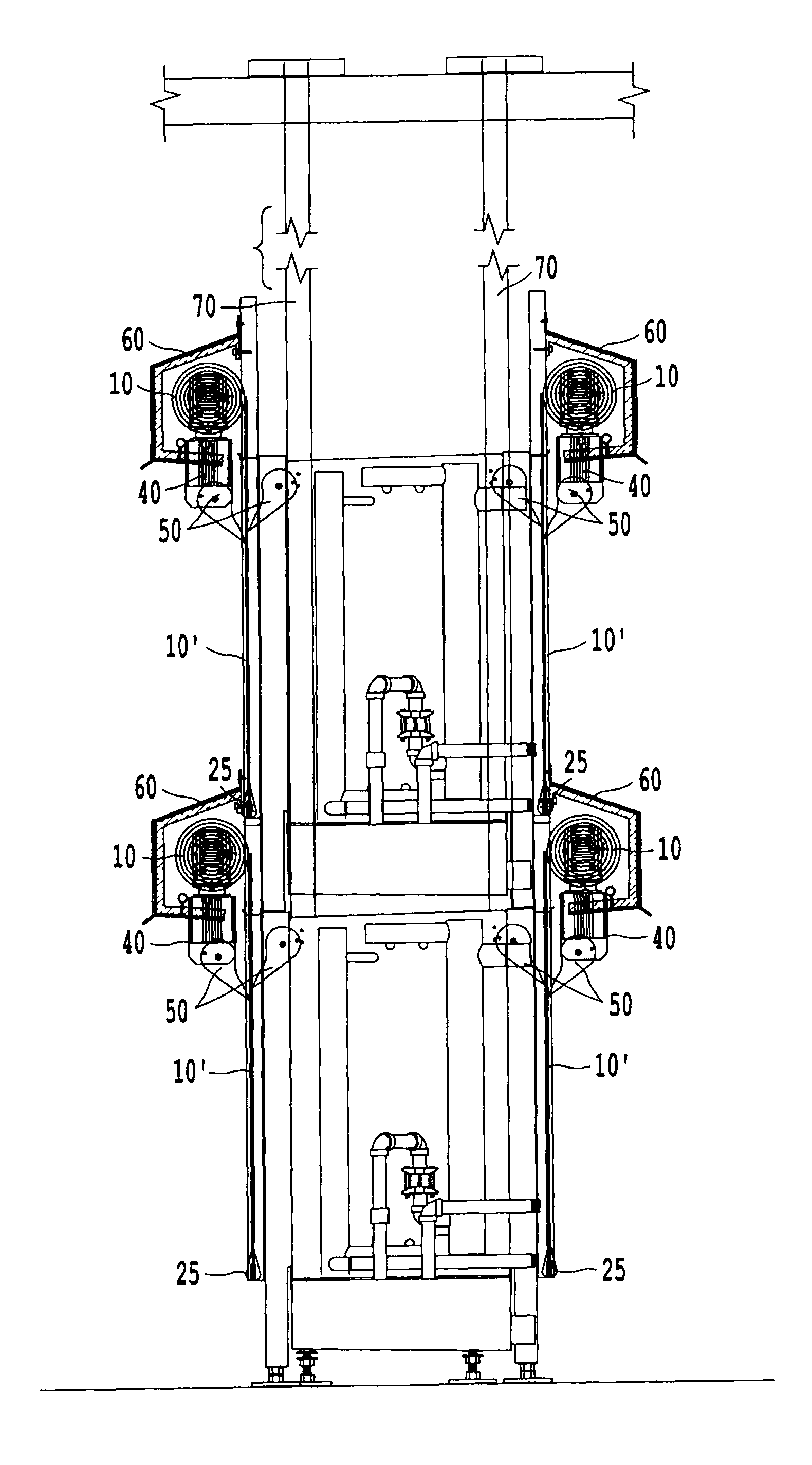
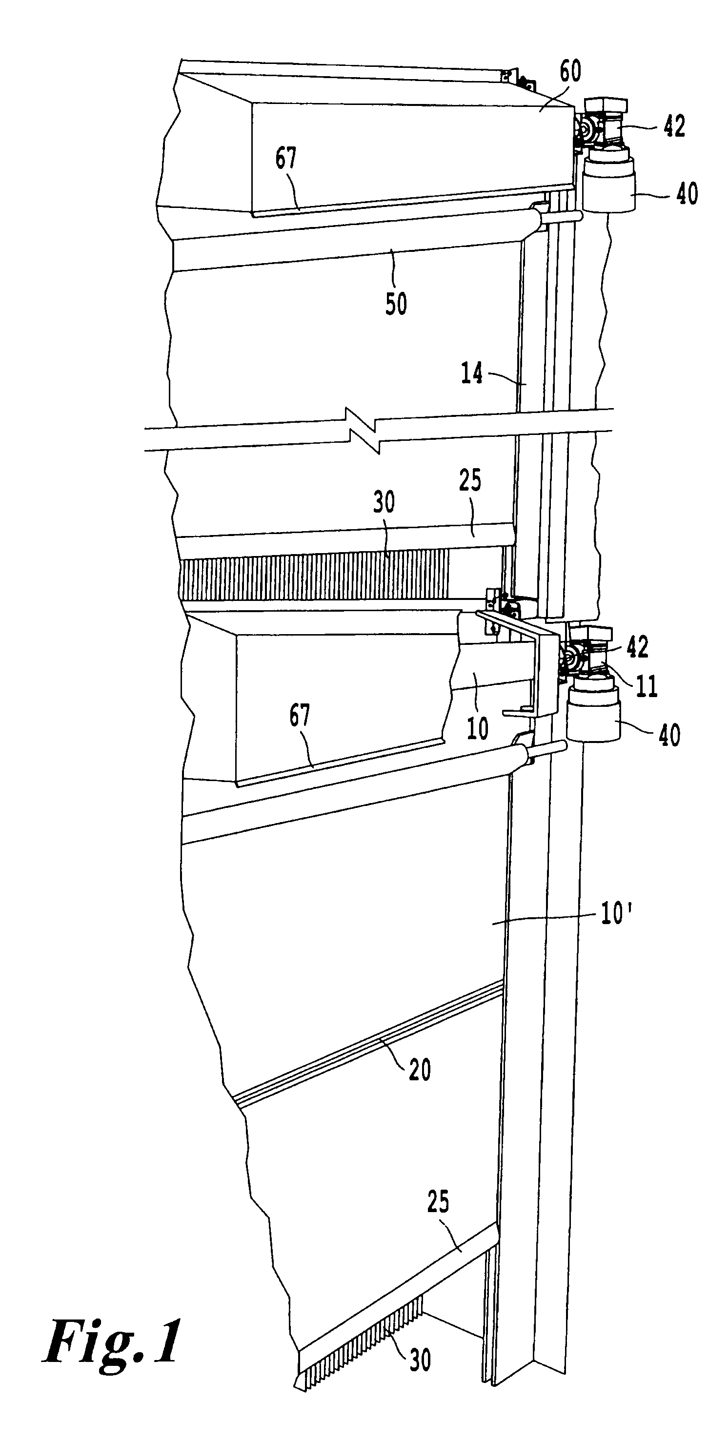
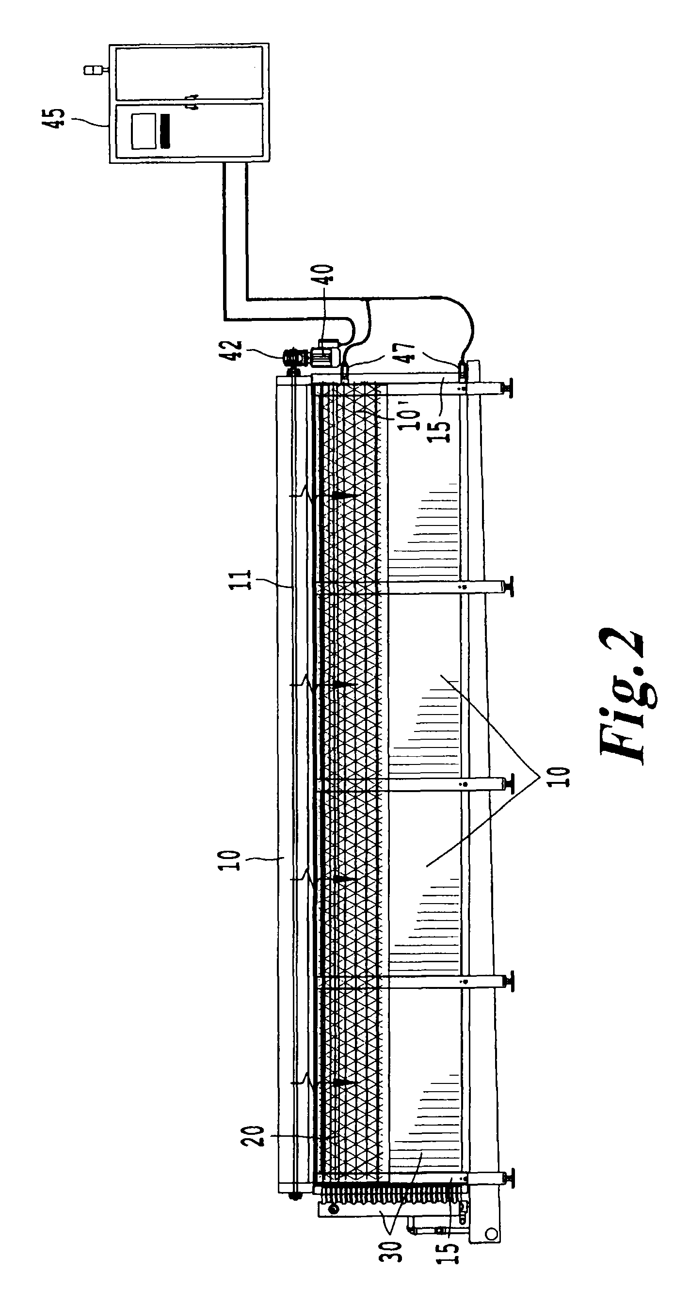
[0024]With reference to FIG. 1, one example of a door system 1 is shown in perspective. In this arrangement, a door member 10 is shown rolled around a rotatable member or shaft 11. A portion of the door member is shown in an unrolled state and is designated 10′. The door member 10 shown in FIG. 1 and rotatable member 11 extend in a horizontal direction, but other orientations are sometimes used. For example, in some applications, the rotatable member 11 extends in vertical direction or is disposed at an acute angle with respect to the vertical or horizontal directions. Such configurations preferably include a door member 10 sufficiently stiff to roll and unroll in response to rotation of the rotatable member 11 without the help of gravity. In any case, the door member 10 is configured to roll or unroll around an axis of rotation X (shown in FIG. 2). When the door member 10 is in an unrolled state, the door member 10 covers a larger portion of the heat exchanger 30 than when the door...


PUM


Abstract

A heat exchanger door system includes a heat exchanger and a first rotatable member, proximate to the heat exchanger, that rotates about an axis of rotation. The system includes a first door member rolled around the rotatable member and movable from a rolled position to an unrolled position in which the first door member covers more of the heat exchanger than when the door member is in the rolled position.

Description

BACKGROUND OF THE INVENTION[0001]1. Field of the Invention[0002]This invention relates to a movable member configured to partially or fully isolate a heat exchanger from an environment. In one example, the movable member is disposed within a cooling system such as a freezer, and isolates one or more heat exchangers within the freezer from an interior of the freezer during a defrost operation.[0003]2. Description of the Related Art[0004]In cooling systems such as freezers and refrigerators, moisture from the air entering the cooling system through open doors, small passages in the walls or floors, and from the product stored within the cooling system frequently collects on heat exchanger coils and heat exchanger fins in the form of ice. During long operation, ice can accumulate on the coils and fins creating a blockage that impedes the airflow over the heat exchanger and creates a loss in efficiency in operation of the cooling system.[0005]Typical heat exchangers increase or decrease...

Claims


Application Information

Patent Timeline
Patent Type & Authority Patents(United States)
IPC IPC(8): F25D17/06F24F11/02F25B47/02
CPCF28F13/00F28F2270/00F25D21/00F28F2265/02
Inventor HASELDINE, JR., MICHAEL, CYRIL
Owner HASELDINE JR MICHAEL CYRIL
Why Eureka
Try Eureka