Heat Exchanger

a heat exchanger and heat exchange technology, applied in the field of heat exchangers, can solve the problems of deteriorating heat exchange efficiency and frost formation, and achieve the effects of enhancing the bending rigidity of the whole heat exchanger, facilitating heat exchange between air and coolant, and enhancing the heat exchange efficiency of the heat exchanger

Inactive Publication Date: 2014-08-14
SANDEN CORP
View PDF2 Cites 0 Cited by
  • Summary
  • Abstract
  • Description
  • Claims
  • Application Information

AI Technical Summary

Benefits of technology

[0022]According to the present invention, since the heat exchanger units that are adjacent to each other can be firmly connected with the fitting portions that connect the end portions of respective header pipes and with the side plates that connect the end portions of the opposing core portions of the respective heat exchanger units, the bending rigidity of the whole heat exchanger can be enhanced.
[0023]Further, according to the present invention, since the side plates are joined to each other so that the space enclosed with the adjacent core portions and the fitting portions is blocked, by which an air escaping route between cores of the heat exchanger is blocked, allowing the whole amount of air blown at the heat exchanger to enter the core portions. Thus the heat exchange between air and coolant is facilitated, allowing the heat exchange efficiency of the heat exchanger to be enhanced.
[0024]Further, according to the present invention, since the bolt insertion hole is provided on the opposing side plates which are arranged on the positions that both these side plates are not in contact to each other and can block the space in the direction of blowing air onto the core portion, the bolt insertion hole can absorb the errors in dimension and assembly at the side plates, allowing to easily achieve unitization of the heat exchanger, so that a connection between the adjacent core portions can be performed without being shifted to each other in the direction of blowing air onto the core portion, leading to improvement of the external appearance and to enhance downsizing of the heat exchanger.
[0025]Further, according to the present invention, the bolt insertion holes is provided with a diameter larger than the diameter of the bolt, through which the errors in dimension and assembly of the heat exchanger are absorbed at the bolt insertion hole, allowing to easily control the errors in dimension and assembly, leading to enhancement of the productivity of the heat exchanger.
[0026]In addition, according to the present invention, by employing identical side plates which are provided symmetrically to each other at the opposing end portions of adjacent core portions and are arranged in front-back direction to each other along the air blowing direction to the core portions, it allows easily to produce and control the component parts of the heat exchanger, leading further to enhance the productivity of heat exchanger.

Problems solved by technology

However, in this lateral-coolant-flow type heat exchanger, there may often occur frost formation due to condensed water adhering to the surfaces of laterally disposed tubes, when the coolant is evaporated.
If a layer of the frost grows up, there may be caused a deterioration of heat exchange efficiency.

Method used


Image

  • Heat Exchanger
  • Heat Exchanger
  • Heat Exchanger

Examples


Embodiment Construction

[0034]In the following, it will be explained about the embodiments of the present invention referring to the associated figures.

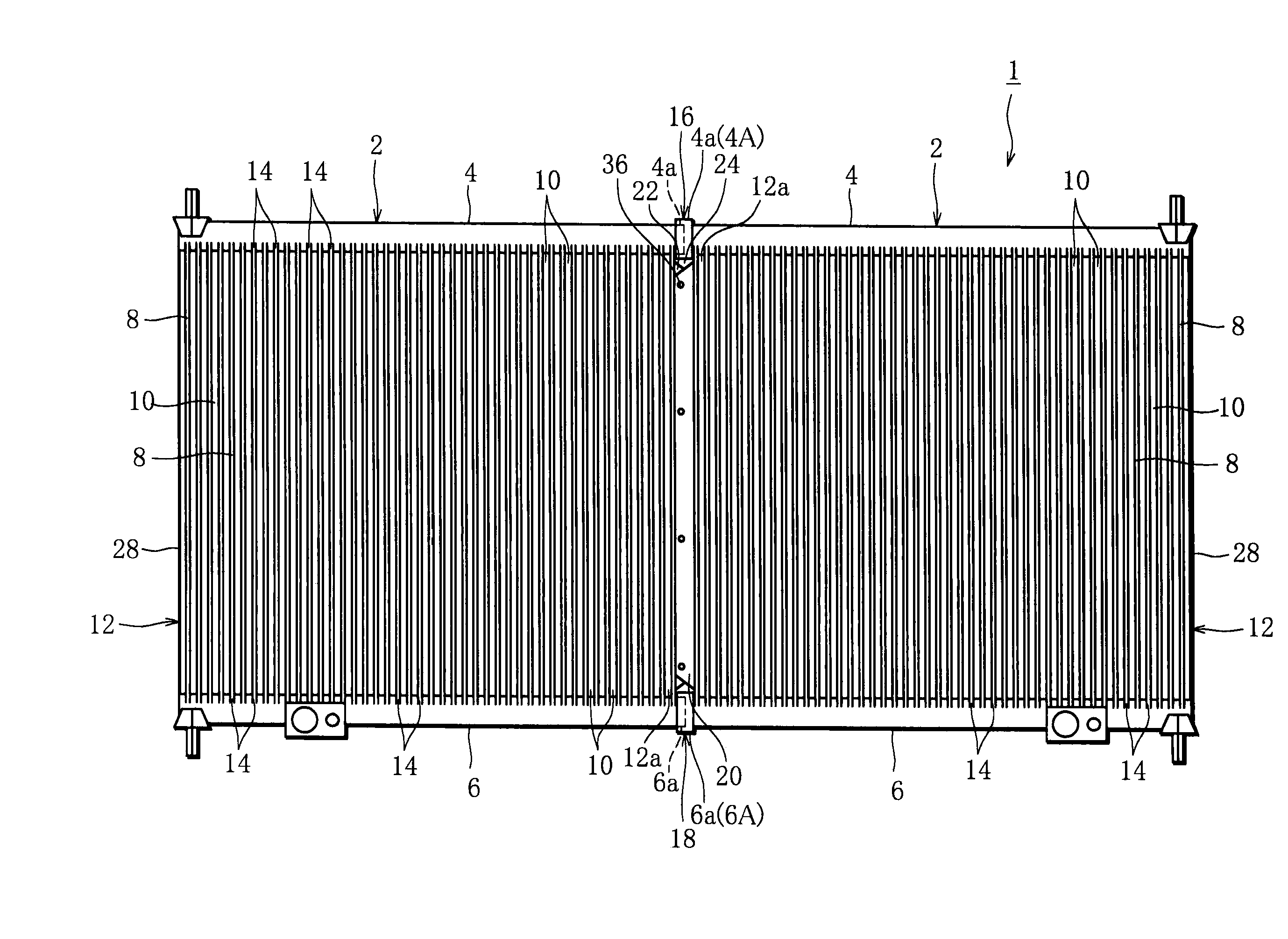
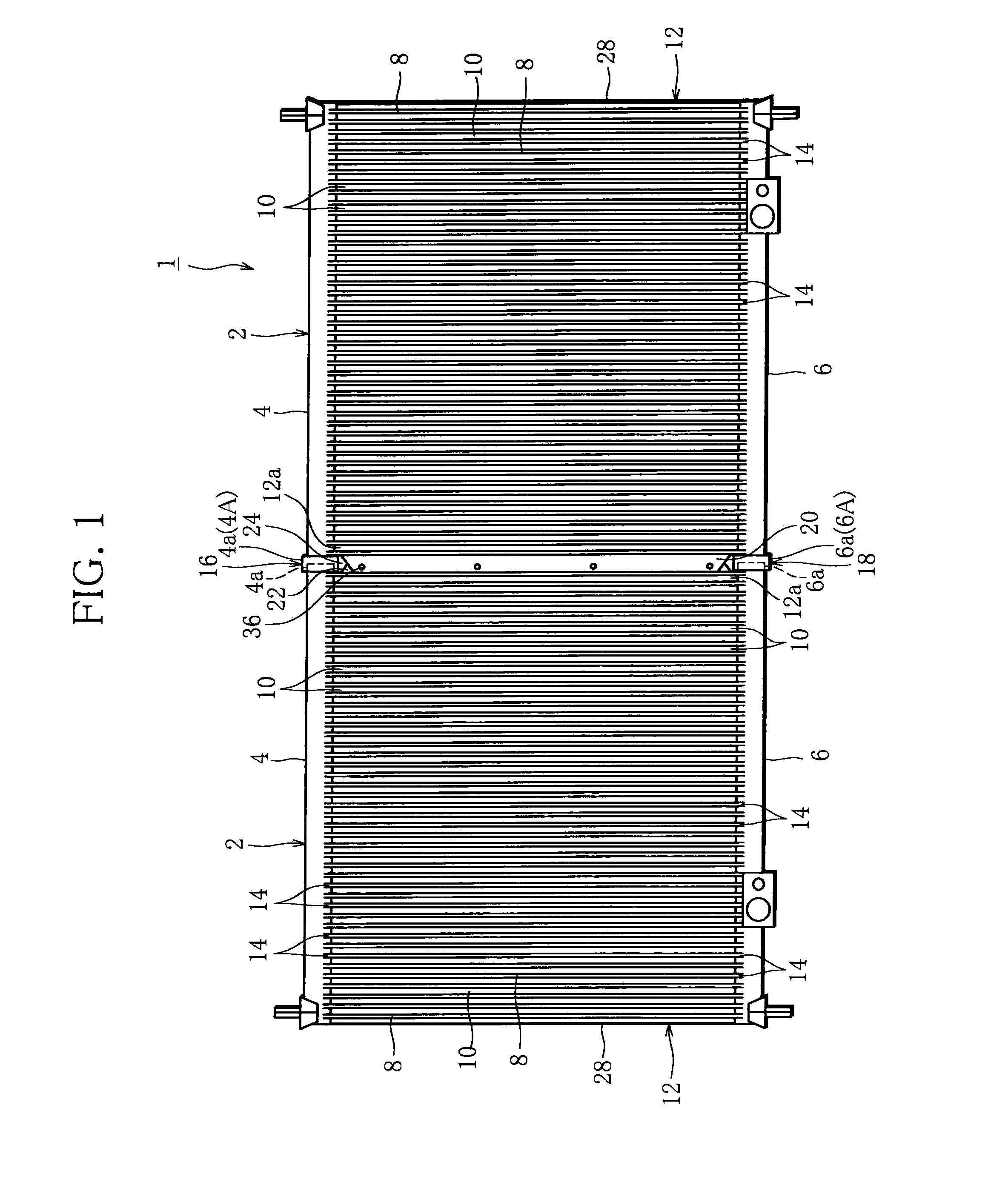
[0035]FIG. 1 is a front view of the heat exchanger 1 of an embodiment according to the present invention. The heat exchanger 1 is of a vertical-coolant-flow type, and is configured with two heat exchanger units 2 being arranged in parallel in the lateral direction.

[0036]The heat exchanger unit 2 comprises upper- and lower header pipes 4, 6 disposed in parallel to each other extending in lateral direction, a plurality of tubes communicating with both header pipes 4,6 and being disposed parallel to each other with a small distance in between the header pipes 4,6, and fins 10 disposed between adjacent tubes 8. These tubes 8 and fines 10 that are layered constitute a core portion of the heat exchanger. The plurality of tubes 8 are connected by blazing at the connecting holes that are provided in regular intervals on the header pipes 4,6.

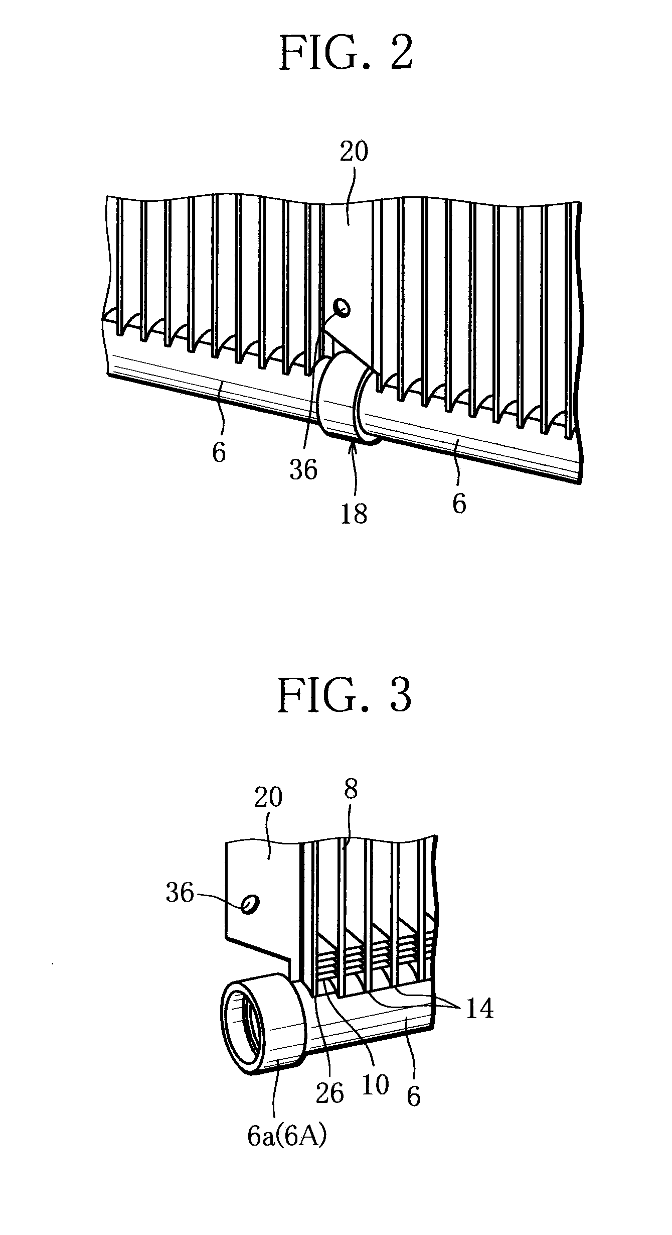
[0037]FIG. 2 shows an en...


PUM


Abstract

A heat exchanger includes a plurality of heat exchanger units, each of which including header pipes (4,6) disposed in parallel to each other, a plurality of tubes (8) communicating with the header pipes and being disposed between the header pipes, fins (10) disposed between adjacent tubes, wherein a core portion (12) of the heat exchanger unit (2) is configured with the tubes and the fins layered therebetween; wherein the plurality of heat exchanger units are disposed in a direction that the tubes and the fins are arranged; and wherein the heat exchanger includes: fitting portions (16,18) which connect respective end portions (4a, 6a) of the header pipes of the heat exchanger units that are adjacent to each other, and side plates (20,22,40,42,46,48) which connect opposing end portions (12a) of respective core portions of the heat exchanger units that are adjacent to each other.

Description

TECHNICAL FIELD[0001]The present invention is concerning a heat exchanger used as an exterior heat exchanger having both functions of condenser and evaporator for a heat pump system of a vehicle air conditioning.BACKGROUND ART [0002]Conventionally, the above referred heat exchanger comprises, for example, a pair of header pipes disposed with a space and in parallel to each other, a plurality of tubes communicating with both header pipes and being disposed parallel to each other with a small distance, and fins disposed between adjacent tubes. These tubes and fines that are layered constitute a core portion of the heat exchanger. In such a heat exchanger, a pair of header pipes are disposed to extend vertically, and a plurality of tubes are disposed to extend laterally, which is called as a lateral-coolant-flow type heat exchanger. In this type of heat exchanger, it is designed so that the length (vertical dimension) of the header pipes is larger than the length of tubes (lateral dime...

Claims


Application Information

Patent Timeline
Patent Type & Authority Applications(United States)
IPC IPC(8): F28F1/12
CPCF28F9/002F28F9/0243F28F9/262F28D1/05366F28D2021/0084F28D2021/0085F28F1/12F28F2275/20
Inventor MATSUMOTO, YUUICHIIINO, YUSUKE
Owner SANDEN CORP
Why Eureka
Try Eureka