Heat exchanger tube

a technology of heat exchanger and heat exchanger tube, which is applied in the direction of heat exchange apparatus, tubular elements, lighting and heating apparatus, etc., can solve the problems of increased turbulence of heat medium which flows inside the tube, increased turbulence, and possible pressure loss, so as to optimize the transfer of heat when liquefaction occurs, and the effect of reducing the turbulen

Active Publication Date: 2021-03-16
WIELAND WERKE AG
View PDF39 Cites 0 Cited by
  • Summary
  • Abstract
  • Description
  • Claims
  • Application Information

AI Technical Summary

Benefits of technology

[0035]In one further advantageous refinement of the invention, a projection can have, at the face facing away from the tube wall, a curved tip whose local curvature radius is decreased starting from the tube wall as the distance increases. This has the advantage that the condensate which is produced at the tip of a projection is transported more quickly to the fin foot as a result of the convex curvature, and the transfer of heat is therefore optimized when liquefaction occurs. At the phase change, here specifically when liquefaction occurs, the focus is on the liquefaction of the vapour and the conduction away from the condensate from the tip to the fin foot. A convexly curved projection forms an ideal basis for the effective transfer of heat therefore.

Problems solved by technology

The projections provide additional ways for a flow of fluid inside the tube and as a result increase the turbulence of the transfer of heat medium which flows inside the tube.
This results in turn in an optimized transfer of heat with the lowest possible pressure loss, since the fluid boundary layer, which impedes good transfer of heat, is interrupted by additionally produced turbulence.
An interruption as a result of the division of the projections also additionally brings about an increase in the turbulence and to an exchange of fluid over the profile of the primary fin, which also brin

Method used


Image

  • Heat exchanger tube
  • Heat exchanger tube
  • Heat exchanger tube

Examples


Embodiment Construction

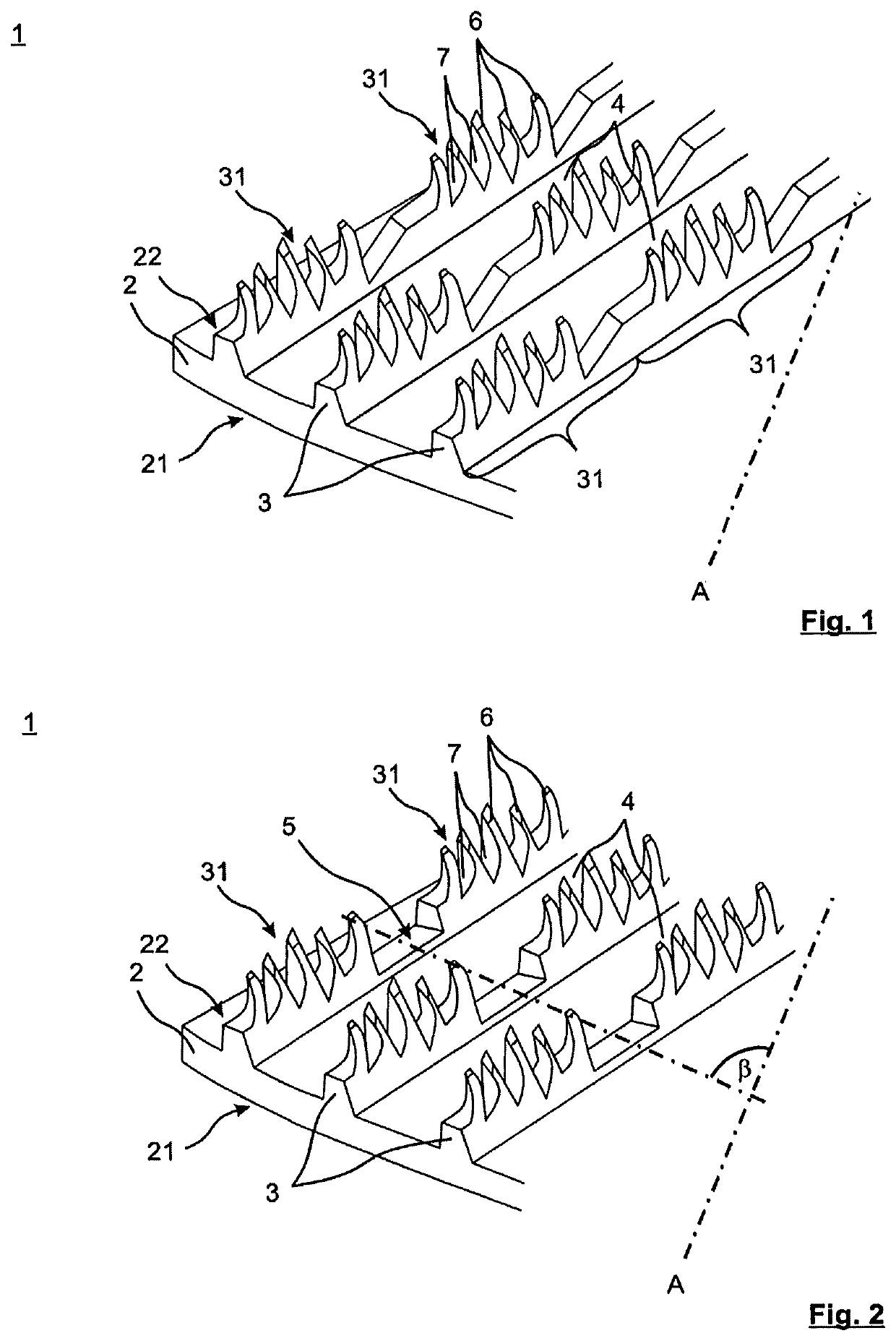
[0054]FIG. 1 shows a schematic, oblique view of a section of the tube of the heat exchanger tube 1 with the inventive structure on the inner tube face 22. The heat exchanger tube 1 has a tube wall 2, an outer tube face 21 and an inner tube face 22. Helically circumferential continuous fins 3 are formed which continuously run from the tube wall 2 on the inner tube face 22. The tube longitudinal axis A runs at a certain angle with respect to the fins. Continuously extending primary grooves 4 are formed between respectively adjacent fins 3.

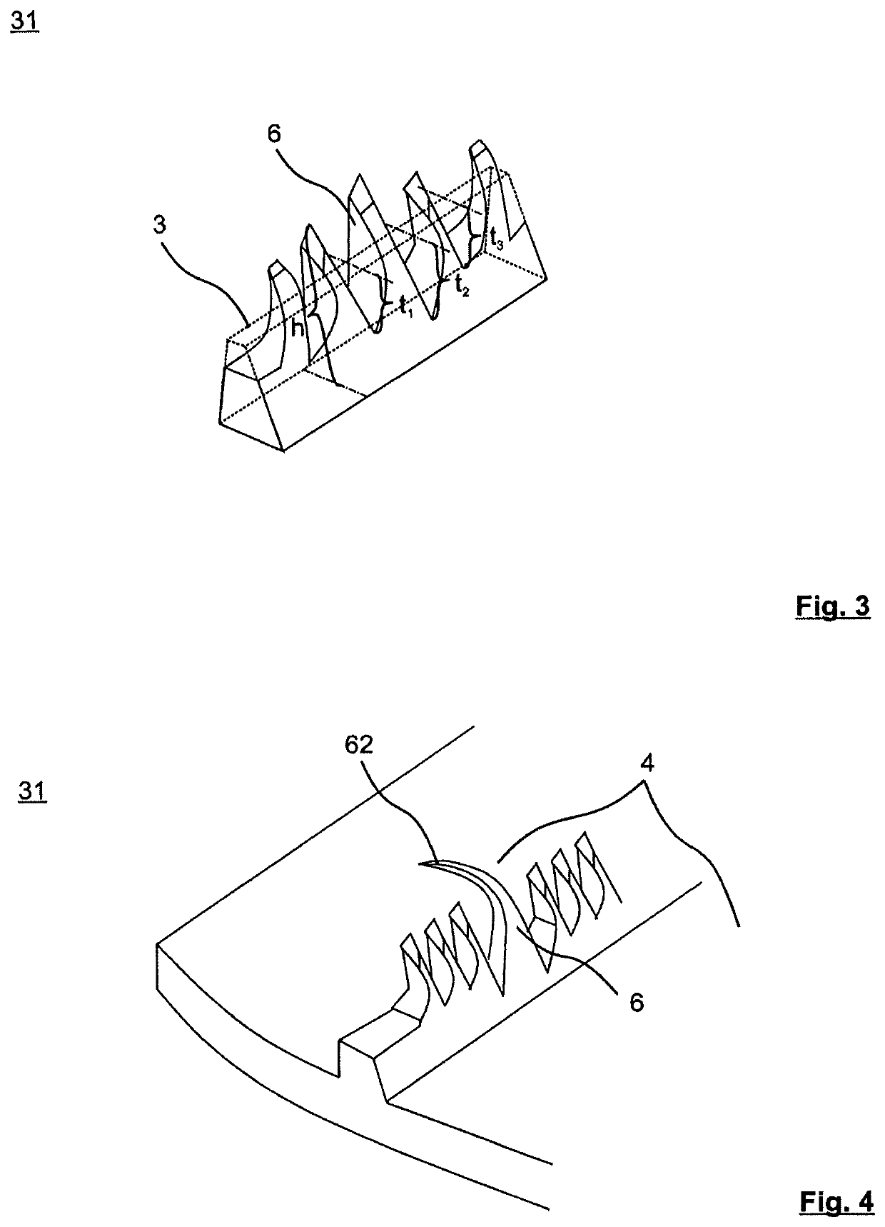
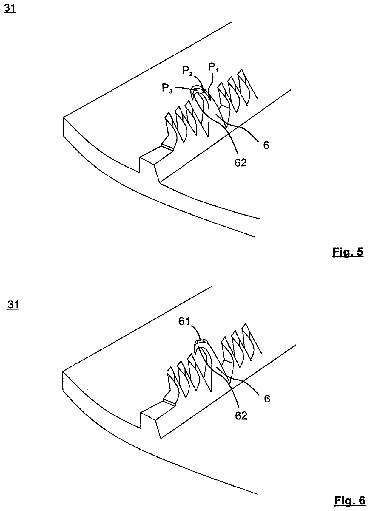
[0055]The fins 3 are subdivided along the fin profile into periodically repeating fin sections 31 which are divided into a multiplicity of projections 6. The projections 6 are formed between primary grooves 4 by making cuts into the fins 3 at a cutting depth transversely with respect to the fin profile to form fin segments and by raising the fin segments in a main orientation along the fin profile.

[0056]In FIG. 1, the fin sections 31 of the fins 3 ar...


PUM


Abstract

The invention relates to a heat exchanger tube (1) having a tube longitudinal axis (A), a tube wall (2), an outer tube face (21) and an inner tube face (22), wherein axially parallel or helically circumferential continuous fins (3) are formed on the outer tube face (21) and/or inner tube face (22) which fins continuously run from the tube wall, and continuously extending primary grooves (4) are formed between respectively adjacent fins (3). According to the invention, the fins (3) along the fin profile are subdivided into periodically repeating fin sections (31) which are divided into a multiplicity of projections (6) with a projection height (h), wherein the projections (6) are formed between primary grooves (4) by making cuts into the fins (3) at a cutting depth transversely with respect to the fin profile to form fin segments and by raising the fin segments in a main orientation along the fin profile.

Description

TECHNICAL FIELD[0001]The present invention relates to a heat exchanger tube having a tube wall, an outer tube face, an inner tube face, axially parallel or helically circumferential continuous fins formed on the outer tube face and / or the inner tube face which fins continuously run from the tube wall, and continuously extending primary grooves formed between respectively adjacent fins.BACKGROUND AND SUMMARY[0002]Heat exchange occurs in many fields of refrigeration and air-conditioning technology as well as in processing and energy technology. In these fields, tubular bundle heat exchangers are frequently used to exchange heat. In many applications, a liquid, which is cooled or heated as a function of the direction of the heat flow, flows on the inner tube face here. The heat is output to the medium located on the outer tube face or extracted therefrom.[0003]It is generally known that, instead of smooth tubes, structured tubes are used in tubular bundle heat exchangers. The transfer ...

Claims


Application Information

Patent Timeline
IPC IPC(8): F28F1/14F28F1/36F28F1/40F28F1/42F28F1/18
CPCF28F1/36F28F1/18F28F1/40F28F1/422
Inventor GOTTERBARM, ACHIMLUTZ, RONALDEL HAJAL, JEANKNAB, MANFRED
Owner WIELAND WERKE AG
Why Eureka
Try Eureka