Thin rubber member producing method, rubber rolling device and rubber rolling method

a production method and rubber roller technology, applied in butter manufacturing, filament/thread forming, auxillary shaping apparatus, etc., can solve the problems of inability to increase width accuracy, and inability to achieve high-quality widths

Inactive Publication Date: 2005-06-02
BRIDGESTONE CORP
View PDF25 Cites 37 Cited by
  • Summary
  • Abstract
  • Description
  • Claims
  • Application Information

AI Technical Summary

Benefits of technology

[0066] Next, an operation and an effect of the rubber roller according to claim 9 will be explained.
[0067] If a distance from the metering discharge pump to a head is short, uneven filling of an unvulcanized rubber into the head occurs. Accordingly, the rectifier tube is interposed between the metering discharge pump and the cap, and uneven filling of the unvulcanized rubber into the head can be prevented, whereby the unvulcanized rubber can be maintained properly and stabilized.

Problems solved by technology

Especially when both edge portions of the rolled rubber sheet to be molded are provided with inclining taper portions, it becomes difficult to obtain a width with high accuracy.
The smaller (the more acute) the inclination angle of the taper portion of the rolled rubber sheet in order to improve a quality, the more difficult the increase of the width accuracy, thus making it more necessary to precisely cut the rolled rubber sheet into a required configuration.
Accordingly, it becomes disadvantageous in respect of space, troubles may easily occur, and there is also a concern that productivity may be inhibited.
The 1-roller die 405 is heavy, requires high manufacturing cost, and outputs a small amount of a leakage of rubber thus necessitating a periodical treatment.
Accordingly, a phenomenon in which taper portions are corrugated with time, whereby a problem is caused in that sheet quality may deteriorate.
In other words, when a low quality elongated rubber strip is used, as a matter of course, it is difficult to obtain a high quality rubber strip.

Method used


Image

  • Thin rubber member producing method, rubber rolling device and rubber rolling method
  • Thin rubber member producing method, rubber rolling device and rubber rolling method
  • Thin rubber member producing method, rubber rolling device and rubber rolling method

Examples


first embodiment

[0126] With reference to the drawings, i.e., FIGS. 1 to 5, a method of manufacturing a thin rubber member according to a first embodiment of the present invention will be explained, hereinafter.

An Apparatus for Manufacturing an Elongated Rubber Strip

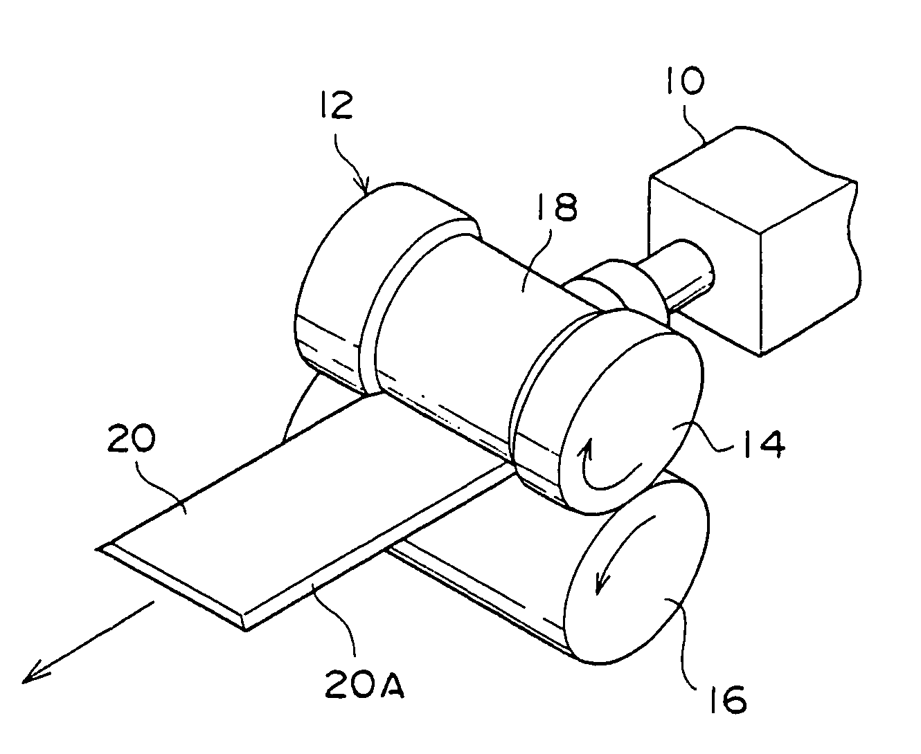
[0127] As shown in FIG. 1, a roller die 12 is disposed at a discharge outlet side of an extruder 10.

[0128] The roller die 12 comprises an upper roller 14 and a lower roller 16.

[0129] A wide groove 18 is formed at the center of the upper roller 14.

[0130] The depth of the groove 18 is fixed in a roller axial direction, and groove walls at both sides of the groove 18 are inclined at an angle of about 87° with respect to a roller radial direction.

[0131] The upper roller 14 and the lower roller 16 are rotated by an unillustrated driving apparatus in a direction of arrow.

[0132] The extruder 10 extrudes an unvulcanized rubber composition, that is supplied into a hopper (not shown), from the discharge outlet. The rubber composition, whic...

second embodiment

[0153] Next, with reference to FIGS. 6 to 8, a method of manufacturing a thin rubber member according to a second embodiment of the present invention will be explained.

An Apparatus for Manufacturing a Rubber Sheet

[0154] As shown in FIG. 6, in the present embodiment, first, the elongated rubber strip 20 extruded from the roller die 12 (not shown in FIG. 6) is spirally wound around an outer circumferential surface of a drum 40, which has a fixed diameter and rotates in a direction of arrow, with the taper portions 20A overlapped with one another.

[0155] Next, as shown in FIG. 7, both end portions in the drum axial direction of the elongated rubber strip 20, which is spirally wound around the drum, are trimmed by a cutter or the like so as to be in parallel to the drum circumferential direction.

[0156] During the trimming, the cutter is inclined at an angle of 45° with respect to the sheet surface so that the cut surface forms an angle of 45° with respect to the sheet surface.

[0157...

third embodiment

[0170] With reference to FIGS. 11 to 14, a rubber roller 110 according to a third embodiment of the present invention will be explained.

[0171] An outlook perspective view of the rubber roller 110 according to the present embodiment is shown in FIG. 11, and a side view thereof is shown in FIG. 12.

[0172] The rubber roller 110 sequentially molds an elongated rubber strip 101 for forming a thin gauge sheet as a tire structural member.

[0173] The elongated rubber strip 101 is molded into a flat strip shape having taper portions 101A and 101A in which both edge portions are inclined in a tapered manner, and while the taper portions 101A are sequentially overlapped with one another, a thin gauge sheet is formed.

[0174] As shown in FIGS. 11 and 12, the rubber roller 110 comprises an extruder 111, a gear pump 112, a rectifier tube 113, a cap 115 of a head 114, and a pair of calendar roll 116 in this sequential order. An unvulcanized rubber injected into the extruder 111 is molded, and sequ...


PUM

PropertyMeasurementUnit
angleaaaaaaaaaa
angleaaaaaaaaaa
angleaaaaaaaaaa

Abstract

To provide a method of manufacturing a thin rubber member capable of accommodating various-size and manufacturing a thin rubber member having a constant thickness.
In the first step, a long rectangular rubber strip having taper portions formed at both end portions in a transverse direction of the long rectangular rubber strip is cut to a predetermined length to thereby form a plurality of segmented rubber strips 36.
In the second step, taper portions 36B at both end portions in a transverse direction of the rubber strip 36 are overlapped with one another, and a plurality of the segmented rubber strips 36 is connected to each other in the transverse direction, whereby a rubber sheet 38, the end portions of which are tapered and which has a large area, can be formed.
Further, the rubber sheet 38 that can accommodate various sizes can be obtained by changing the length of the segmented rubber strip 36 and the number of connections thereof.

Description

BACKGROUND OF THE INVENTION [0001] 1. Field of the Invention [0002] The present invention relates to a method of manufacturing a thin rubber member, a rubber roller for forming an elongated rubber strip which is suitably designed for use in the method of manufacturing a thin rubber, and more particularly, to a method of rolling a rubber for forming the elongated rubber strip that is suitably designed for use in the method of manufacturing a thin rubber. [0003] 2. Background Art [0004] Conventionally, a rubber member used for a tire, for example, a rubber sheet such as an inner liner or the like has been manufactured by a method of sheeting a rubber member by a so-called 2-roller die 300 as shown in FIG. 20, a method of sheeting a rubber sheet by a so-called 1-roller die 2 as shown in FIG. 21, or a method using four calendar rolls (not shown). [0005] As for an inner liner 303 formed by such conventional methods as described above, the inner liner 303 during sheeting has a width W tha...

Claims


Application Information

Patent Timeline
Patent Type & Authority Applications(United States)
IPC IPC(8): B29C48/08B29C48/35B29C48/92B29C53/78B29C65/00B29C69/00B29D30/00B29D30/52
CPCB29C47/0019B29C47/92B29C47/0066B29C47/32B29C53/78B29C66/02241B29C66/435B29C69/003B29C2793/0027B29C2793/009B29C2947/92019B29C2947/92104B29C2947/92133B29C2947/9239B29C2947/92447B29C2947/92514B29C2947/9259B29C2947/926B29C2947/92619B29C2947/92628B29C2947/92857B29C2947/92885B29C2947/92942B29D30/16B29D30/30B29D2030/0682B29K2021/00B29K2105/256B29L2007/007B29C47/003B29C66/49B29C66/1162B29C66/14B29C66/4322B29C66/4329B29C65/00B29C66/71B29C48/92B29C48/07B29C48/12B29C48/0022B29C48/35B29C2948/92019B29C2948/92104B29C2948/92133B29C2948/9239B29C2948/92447B29C2948/92514B29C2948/9259B29C2948/926B29C2948/92619B29C2948/92628B29C2948/92857B29C2948/92885B29C2948/92942B29C48/08
Inventor OGAWA, KENJIKATA, TAKEHIRO
Owner BRIDGESTONE CORP
Why Eureka
Try Eureka