
System and method for supply distribution

a technology of supply distribution and system, applied in the direction of constant-current supply dc circuit, process and machine control, instruments, etc., to achieve the effect of preventing interruption of operating appliances, simple and easy use, and economical manufacturing cos

Inactive Publication Date: 2005-06-02
MERDJAN BRUCE
View PDF28 Cites 20 Cited by
  • Summary
  • Abstract
  • Description
  • Claims
  • Application Information

AI Technical Summary

Benefits of technology

"The present invention is a system and method for energy supply distribution that uses pre-determined truth tables to prioritize and divide an operational supply among multiple appliances or machines. The invention allows for the efficient management of supply distribution to maintain a balance between supply and demand, while also allowing for the installation of smaller equipment in houses or buildings. It also prioritizes the order in which appliances or utilities are operated, prevents interruption of operating appliances upon turning off another appliance, and allows for the simultaneous operation of multiple appliances within the limits set by the supply capacity. The invention is simple and easy to use, and is also economical in cost to manufacture."

Problems solved by technology

The management of supply distribution to multiple appliances, areas, or machinery may be required due to capacity limits on the power and utility supply grid or a limited amount of heating capacity or air supply distribution system within a home or building available for use.

Method used


Image

  • System and method for supply distribution
  • System and method for supply distribution
  • System and method for supply distribution

Examples


Embodiment Construction

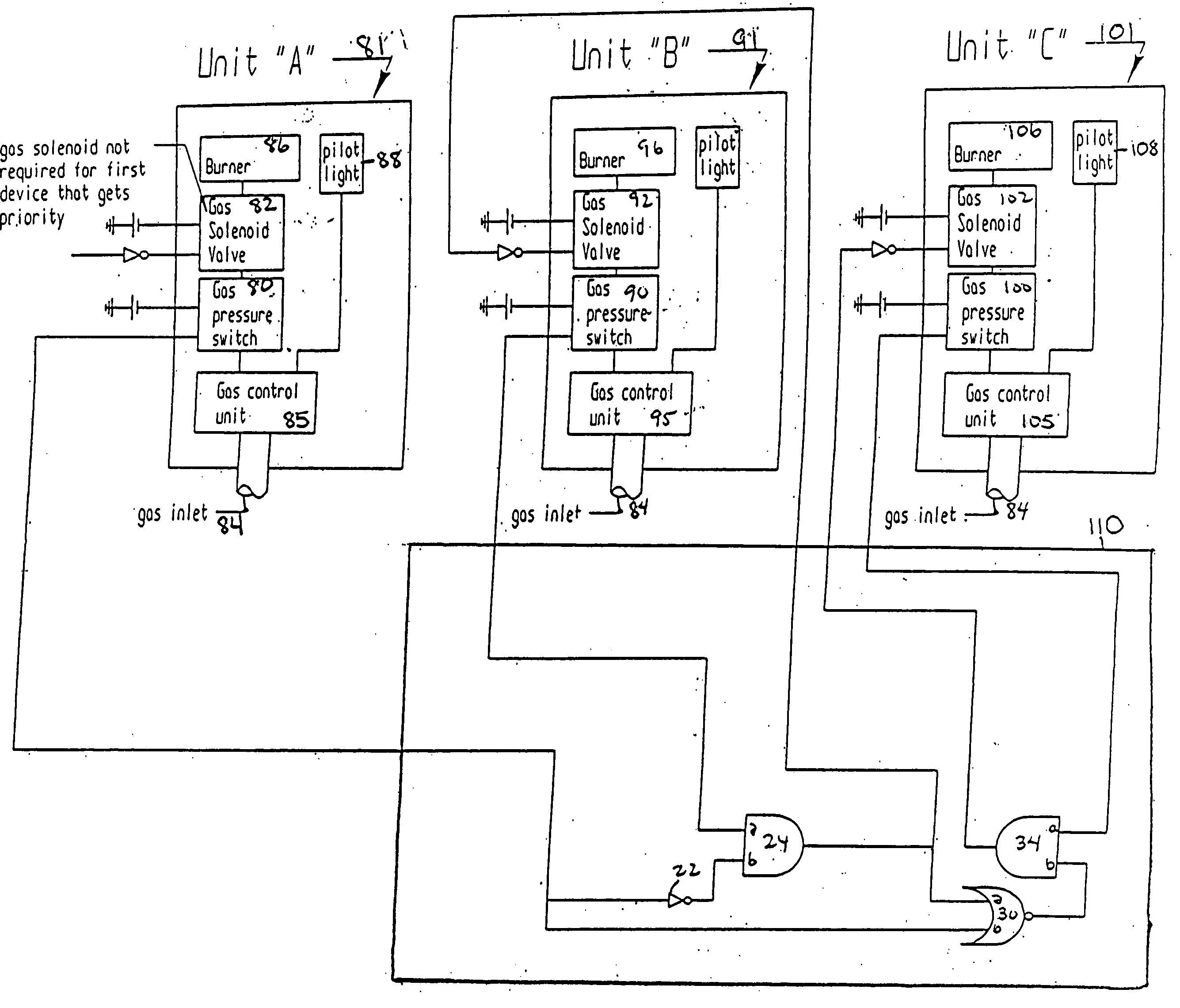
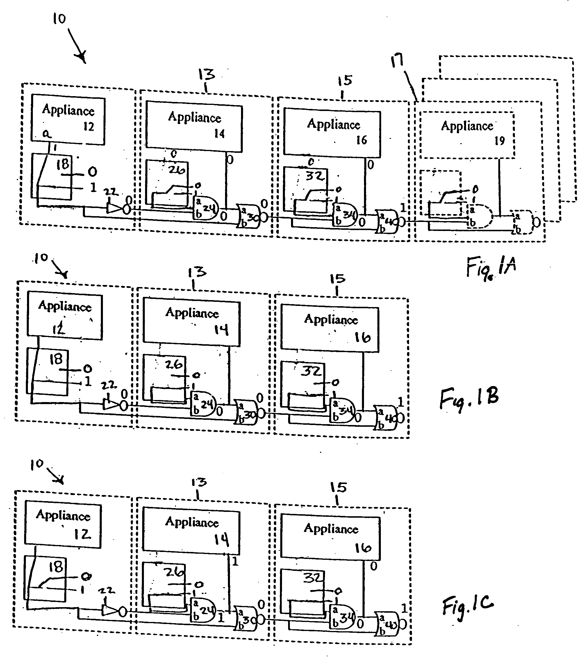
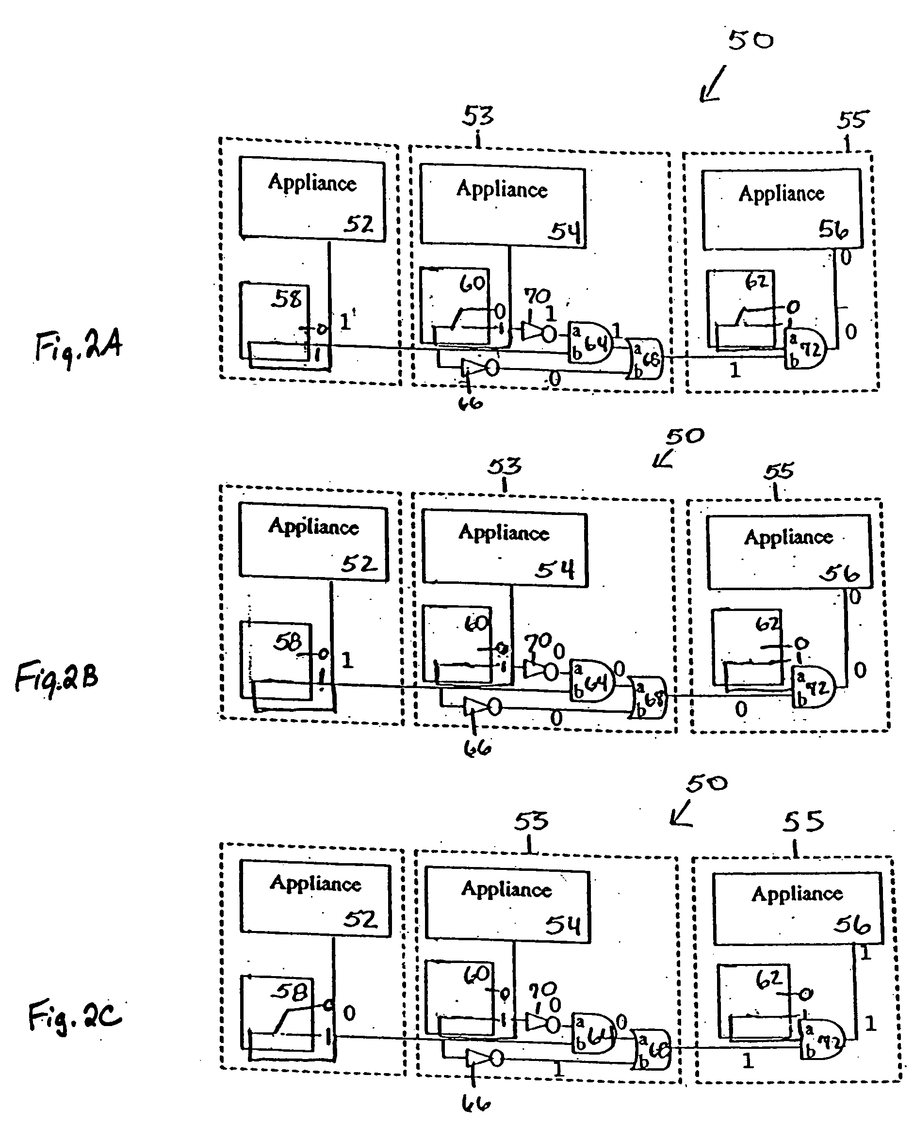
[0031] Turning now descriptively to the drawings, in which similar reference characters denote similar elements throughout the several views, FIGS. 1 through 5 illustrate the energy supply distribution system and method of the present invention. The following discussion describes in detail exemplary embodiments of the invention. This discussion should not be construed, however, as limiting the invention to those particular embodiments, practitioners skilled in the art will recognize numerous other embodiments as well. For definition of the complete scope of the invention, the reader is directed to appended claims.

[0032] In one exemplary application for the present invention, a gas fired boiler and a gas fired instantaneous or tank-less hot water heater are considered. Assuming, for this example, the boiler consumes 125,000 Btu / hr of natural gas and the instantaneous hot water heater consumes 117,000 Btu / hr of natural gas. The two appliances used simultaneously would require 242,000...


PUM


Abstract

A system and method for distributing a supply to plurality of machinery or appliances. The supply may be any of oil, gas, electrical power, water, heated and cooled air, etc. the plurality of appliances can include any of gas and oil powered devices, electrical devices, rooms having HVAC ductwork, etc. The distribution of the operating supply is provided by prioritizing the appliances with a predetermined priority. The appliances are connected in a series connection in order of priority. When any appliance is determined to be in an “ON” state of operation subsequently connected appliances are prevented from operating. Alternatively, when more than one appliance is able to operate simultaneously using the operating supply, the appliances may be divided into a plurality of groups. The plurality of groups include a group for each possible combination of appliances and each group is prioritized. Operating supply is provided to the group having the highest priority with all appliances in the group being determined to be in an “ON” state of operation.

Description

BACKGROUND OF THE INVENTION [0001] 1. Field of the Invention [0002] The present invention relates generally to resource sharing systems and, more specifically, to energy supply distribution systems utilizing pre-determined truth tables to prioritize and divide an operational supply among a plurality of units or appliances. The invention discloses managing distribution of a supply such as electrical power, combustible fuel, e.g., gas and oil, water, compressed air, and heat to maintain a balance between the supply and the demand. The management of supply distribution to multiple appliances, areas, or machinery may be required due to capacity limits on the power and utility supply grid or a limited amount of heat capacity or air supply distribution system within a home or building available for use. A valve or control will selectively permit use of appliances, ductwork, or machinery in a manner as not to exceed the supply capacity of the power grid, utility grid or the distribution. A...

Claims


Application Information

Patent Timeline
Patent Type & Authority Applications(United States)
IPC IPC(8): H02J1/00H02J3/14
CPCH02J3/14H02J2310/14Y04S20/222Y04S20/242Y02B70/30Y02B70/3225
Inventor MERDJAN, BRUCE
Owner MERDJAN BRUCE
Learn More