
Interchangeable horizontally and vertically laser suitable for use in small spaces

a laser and small space technology, applied in the direction of instruments, reference lines/planes/sectors, optical resonator shape and construction, etc., can solve the problems of not being able to orient a typical pipe laser and the inability of typical pipe lasers to lay pipe systems, etc., to achieve accurate level orientation and accurate positioning

Active Publication Date: 2005-06-02
SPECTRA PRECISION (USA) LLC
View PDF30 Cites 13 Cited by
  • Summary
  • Abstract
  • Description
  • Claims
  • Application Information

AI Technical Summary

Benefits of technology

[0005] The present invention overcomes the disadvantages of previously known devices by providing a drive leveling device for a laser transmitter that retains an accurate level orientation within its housing and can be accurately positioned in at least two orthogonal axes.
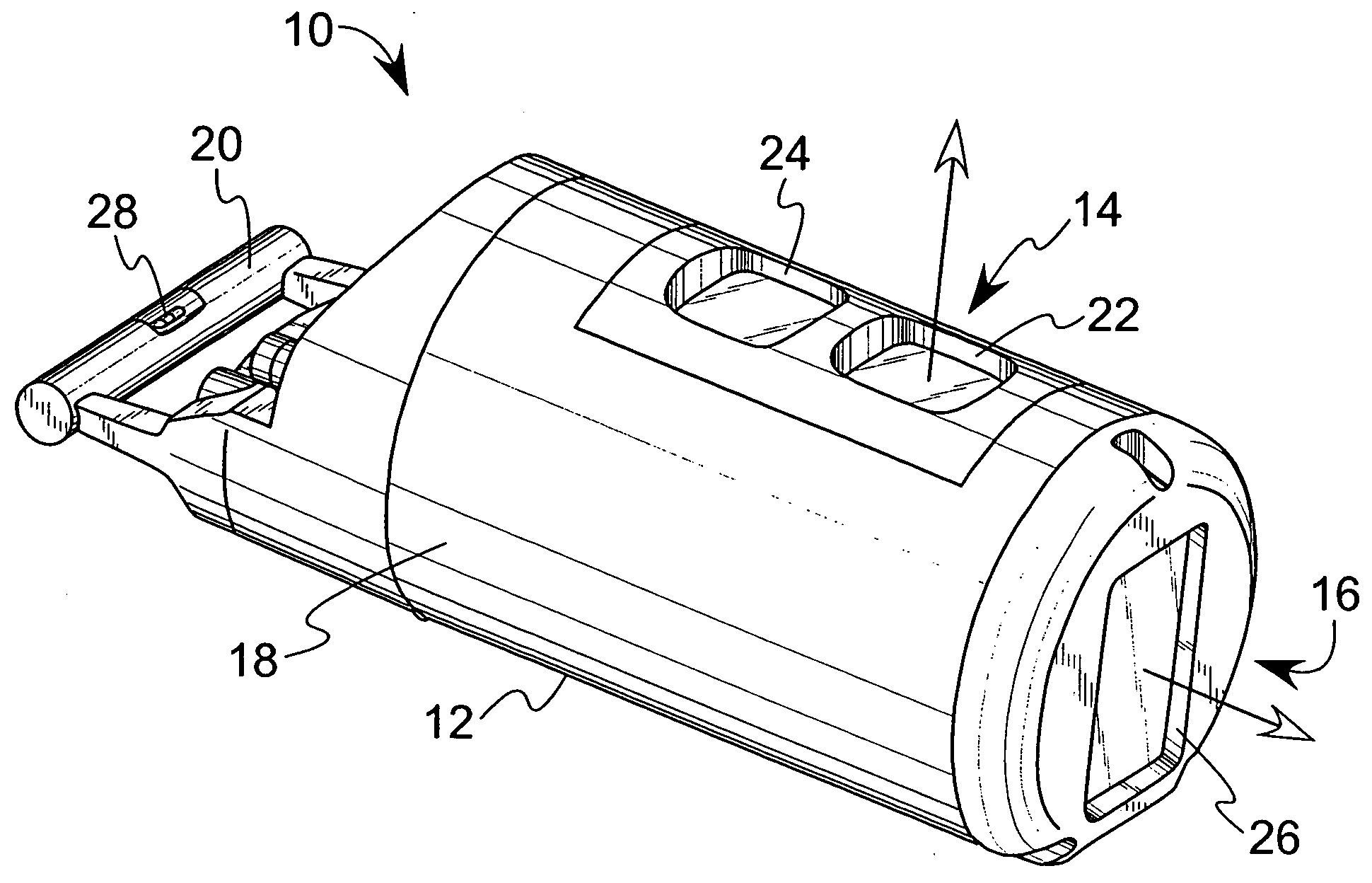
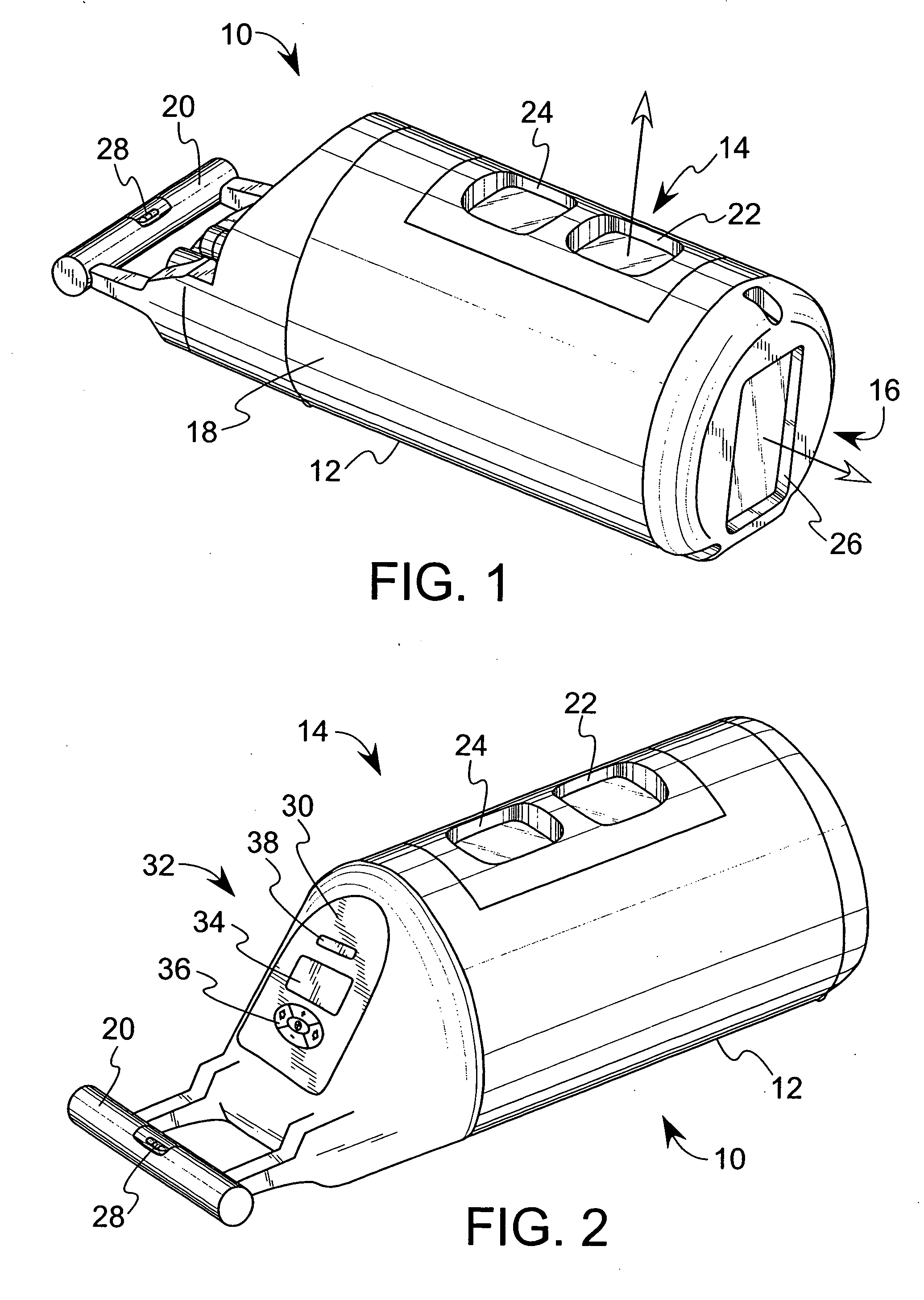
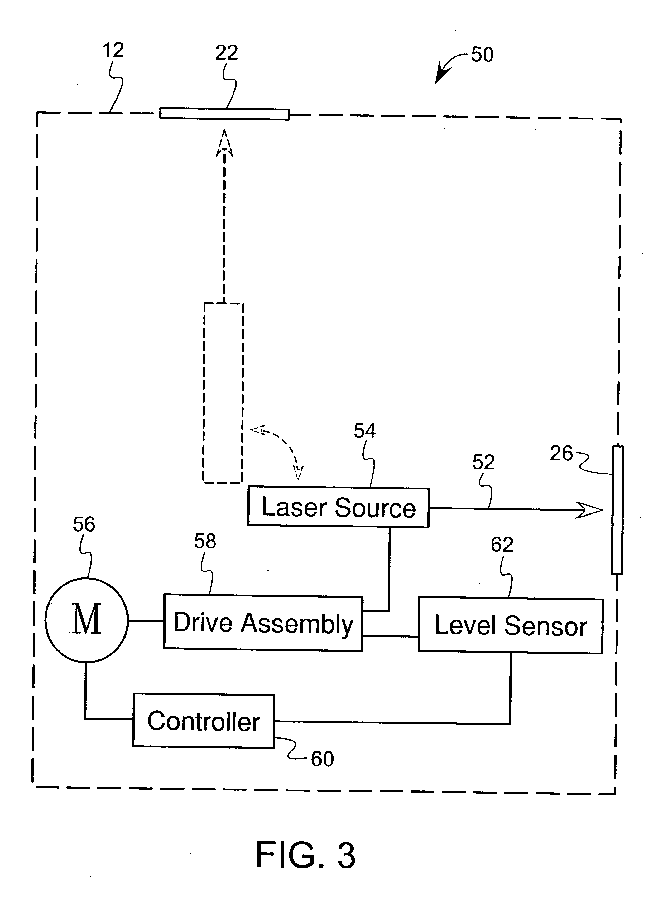
[0006] According to an embodiment of the present invention, a laser transmitter comprises a housing having a first laser exit window and a second laser exit window. A drive device within the housing is operatively configured to rotatably orient a laser source such that a reference beam from the laser source exits the housing through a select one of the first and second laser exit windows as a collimated laser output beam. The first and second laser exit windows may be oriented with respect to the housing in substantially orthogonal planes for example. Such an arrangement allows the laser transmitter to be used when the housing is oriented both vertically and horizontally. Accordingly, the laser transmitter is suitable for use in small spaces such as pipes and sewers.

Problems solved by technology

Due to the space constraints of the clean out and the associated relatively small diameter pipe sections that connect thereto, it is not always possible to orient a typical pipe laser in a clean-out so as to direct the laser beam in a desired direction.
This is because pipe lasers are typically long, generally cylindrical devices that cannot be rotated or easily positioned within the confined spaces of the new clean outs.
Accordingly, typical pipe lasers cannot be used to lay pipe systems that utilize the smaller clean outs.

Method used


Image

  • Interchangeable horizontally and vertically laser suitable for use in small spaces
  • Interchangeable horizontally and vertically laser suitable for use in small spaces
  • Interchangeable horizontally and vertically laser suitable for use in small spaces

Examples


Embodiment Construction

[0021] In the following detailed description of the preferred embodiments, reference is made to the accompanying drawings that form a part hereof, and in which are shown by way of illustration, and not by way of limitation, specific preferred embodiments of the invention. It is to be understood that other embodiments may be utilized and that logical, mechanical and electrical changes may be made without departing from the spirit and scope of the present invention.

[0022] Referring to FIGS. 1 and 2, an exemplary laser transmitter 10 according to an embodiment of the present invention is illustrated. The laser transmitter 10 includes a housing 12 that preferably provides at least some degree of protection from sewage effluents, debris from excavating and other hazards associated with construction sites. As shown, the housing 12 is generally cylindrical and includes a top face 14, a front face 16, a body portion 18 and a handle portion 20. The top face 14 includes a first laser exit wi...


PUM


Abstract

A laser transmitter adapted for use in small spaces such as pipes and sewers includes a housing having two exit windows positioned in generally orthogonal planes. The laser transmitter includes a leveling mechanism that is capable of directing a collimated beam through a select one of the two exit windows, in a generally horizontal direction at a specified grade irrespective of whether the laser transmitter is oriented generally horizontally or generally vertically.

Description

BACKGROUND OF THE INVENTION [0001] The present invention relates in general to alignment instruments used in construction, and in particular, to laser transmitters capable of operating while oriented horizontally or vertically, and which are suitable for use in confined spaces. [0002] Reference laser beam systems are used in numerous surveying and construction applications. In one such application, a laser beam transmitter is used as a direction and grade reference during the installation of sewers and other pipes. Basically, a pipe laser provides a stationary, collimated beam of light that is directed axially along the centerline of a pipe installation. The light beam serves as a visual guide in order to maintain individual sections of pipe in a straight line at a particular grade. A laser beam target is typically placed within each new section of pipe being set into place. The target and the new section of pipe are manipulated until the collimated light is centered on the target. ...

Claims


Application Information

Patent Timeline
IPC IPC(8): G01C15/00
CPCG01C15/002Y10S33/21G01C15/004
Inventor KISHI, KEIJUNKEMP, BRIANKAHLE, KENT W.
Owner SPECTRA PRECISION (USA) LLC
Learn More