Magnetic recording medium

a recording medium and magnetic technology, applied in the direction of digital recording, maintaining head carrier alignment, instruments, etc., can solve the problems of increasing the fluctuation of the fly height per revolution of the magnetic disk, the difficulty of making one area ratio of concaves to convexes, and the difficulty of significantly reducing so as to reduce suppress the fluctuation of the fly height of the head slider. , the effect o

Inactive Publication Date: 2005-06-02
TDK CORPARATION
View PDF3 Cites 54 Cited by
  • Summary
  • Abstract
  • Description
  • Claims
  • Application Information

AI Technical Summary

Benefits of technology

[0010] According to this magnetic recording medium, by forming the second functional area in the servo pattern area, compared to a magnetic recording medium on which no second functional area is formed, it is possible to sufficiently reduce the fluctuation in the fly height of a head slider that passes (travels over) the data track area, the servo pattern area, and the data track area in that order. Accordingly, when recording or reproducing data on the magnetic recording medium, it is possible to avoid a situation where the head slider contacts the surface of the magnetic recording medium.
[0011] Here, it is possible to construct the servo pattern area so that the second functional area is formed between adjacent first functional areas. With this construction, it is possible to form the second functional area without dividing the respective first functional areas into a plurality of parts. Accordingly, since it is possible to use, as the convex / concave patterns that compose the respective first functional areas, the same types of patterns as the convex / concave patterns corresponding to a normal servo pattern area, there is no need to change the types of convex / concave patterns in order for the second functional area to be formed. As a result, tracking servo control can be carried out without any special servo signal detection function being necessary.
[0012] Also, the servo pattern area may be constructed by forming at least an address area and a burst area as the first functional areas and forming the second functional area within at least one area out of the address area and the burst area. With this construction, it is possible to sufficiently suppress the fluctuation in the fly height of the head slider in the same way as the magnetic recording medium described above.
[0013] It is also possible to form the second functional area by forming a convex / concave pattern of a same type as the convex / concave pattern formed in the data track area and embedding the nonmagnetic material in the convex / concave pattern in the second functional area. With this construction, a substantially equal average height can be achieved easily and reliably compared to when the second functional layer is constructed with an average height that is substantially equal to the average height of the data track area using a different type of convex / concave pattern to the convex / concave pattern of the data track area.

Problems solved by technology

However, the above conventional magnetic disk has the following problem.
For this reason, it is extremely difficult to make one area ratio of concaves in the data zone to convexes match another area ratio of concaves in the servo zone to convexes by inverting the convex / concave pattern of a servo pattern on a normal magnetic disk.
Accordingly, with the conventional magnetic disk where the area ratio of the concaves to the convexes is reduced, there is the problem that it is difficult to considerably reduce the fluctuation in the fly height of the head slider.
It should be noted that even when only an area where the fly height is low or only an area where the fly height is high is present inside the servo pattern area, there is still the problem of increased fluctuation in the fly height per revolution of the magnetic disk.

Method used


Image

  • Magnetic recording medium
  • Magnetic recording medium
  • Magnetic recording medium

Examples


Embodiment Construction

[0033] Preferred embodiments of a magnetic recording medium according to the present invention will now be described with reference to the attached drawings.

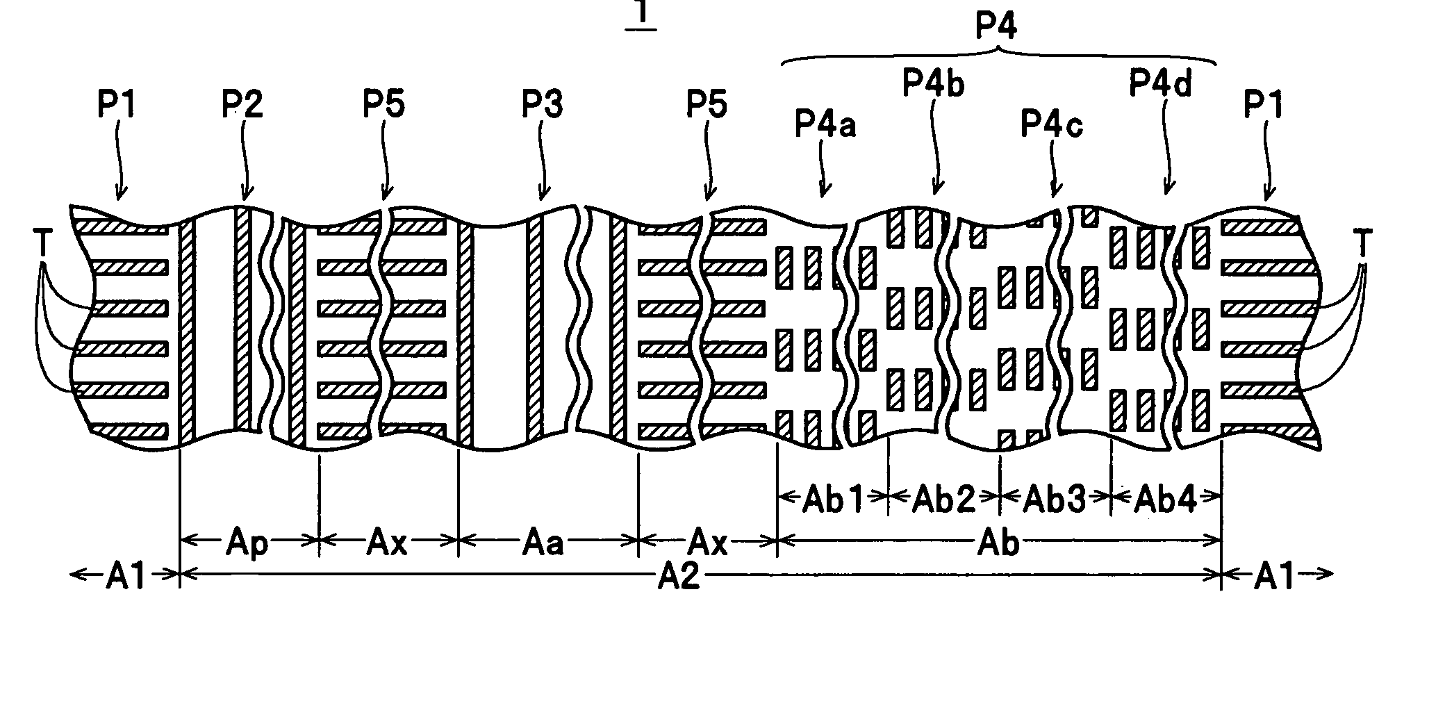
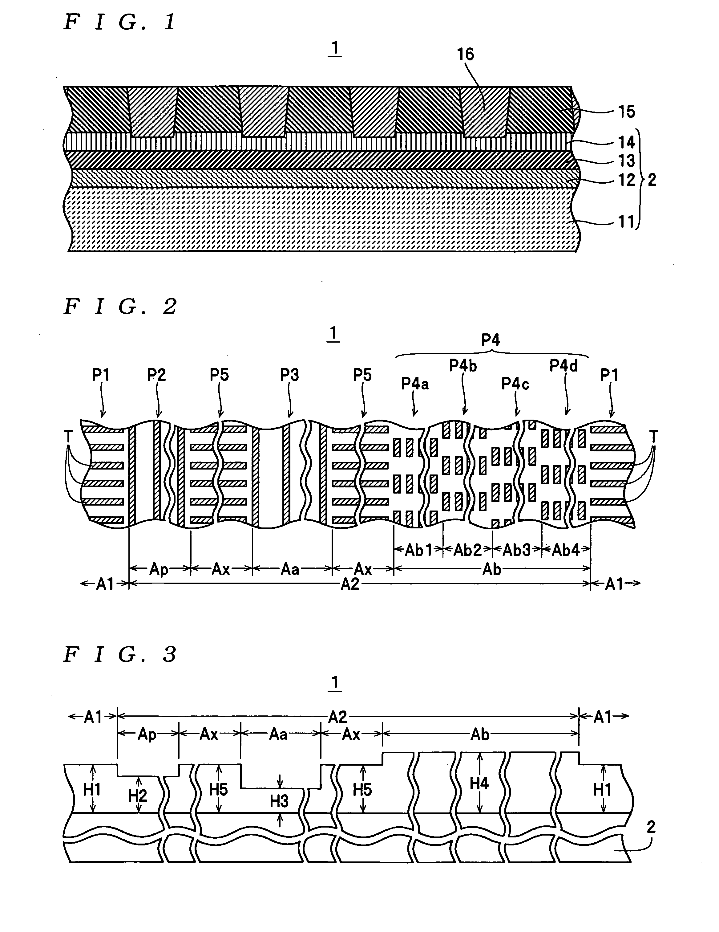
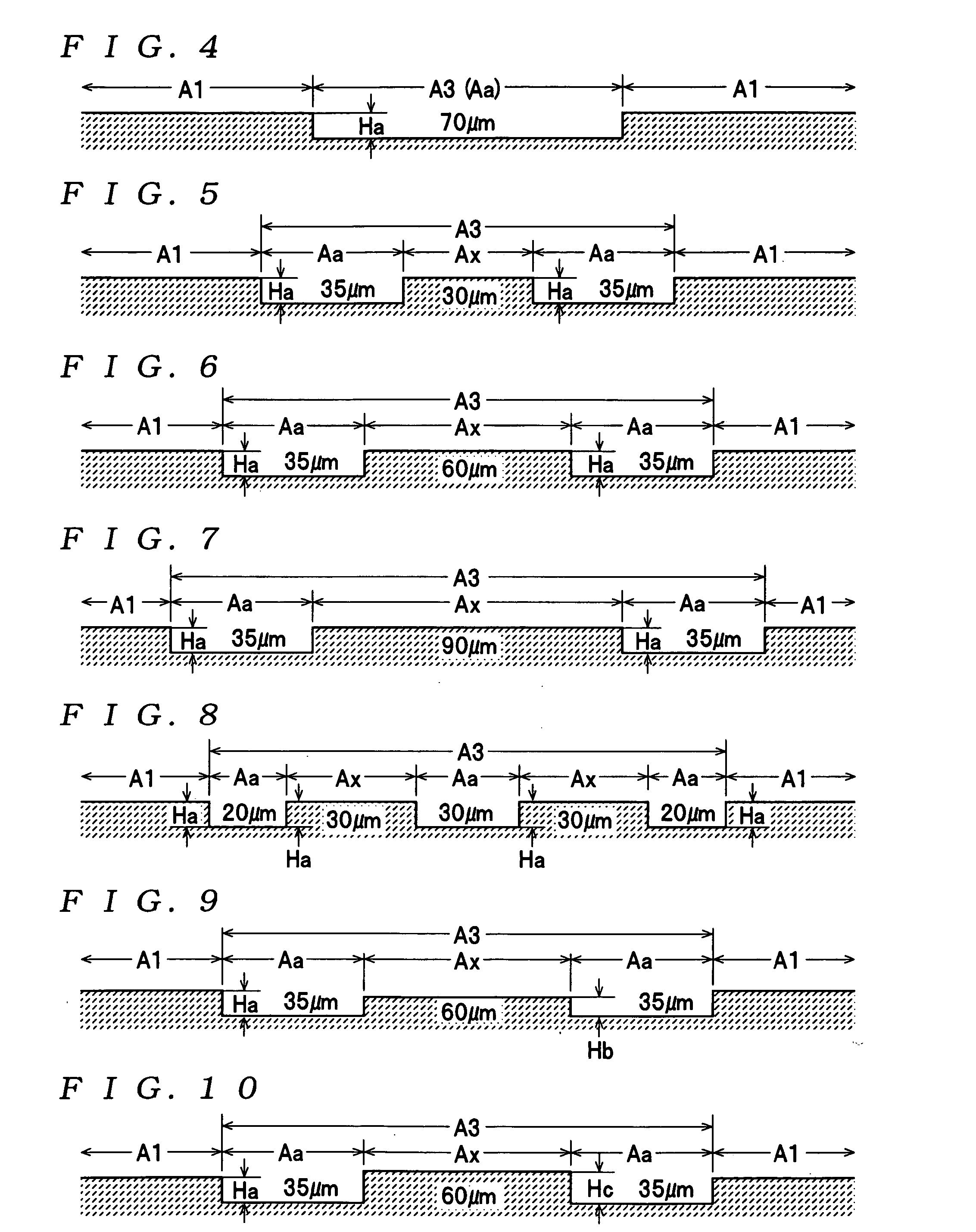
[0034] A magnetic disk 1 shown in FIG. 1 is one example of a magnetic recording medium according to the present invention, and is provided inside a housing together with a spindle motor, head slider (magnetic head) and the like, neither of which is shown, to construct a magnetic disk apparatus. The magnetic disk 1 is a discrete track-type magnetic recording medium (patterned medium) for vertical recording. Convex / concave patterns P1 to P5 (examples of “various types of convex / concave patterns” for the present invention, see FIG. 2) are formed by a ferromagnetic body 15 (a “ferromagnetic material” for the present invention) on a multilayer structure 2 (one example of a “substrate” for the present invention) where a base layer 12, a soft magnetic layer 13, an oriented layer 14, and the like are laminated in that order on a glass ...


PUM

PropertyMeasurementUnit
heightaaaaaaaaaa
lengthaaaaaaaaaa
lengthaaaaaaaaaa

Abstract

A data track area and a servo pattern area are formed on a magnetic recording medium by embedding a nonmagnetic material inside concaves in a plurality of types of convex / concave patterns formed of a magnetic material on a substrate. The servo pattern area includes a plurality of types of first functional areas, in which control signals for disk access are recorded during manufacturing using the convex / concave patterns, and a second functional area, in which a convex / concave pattern of a different type to the convex / concave patterns of the respective first functional areas is formed and in which the nonmagnetic material is embedded so that an average height within the second functional area is substantially equal to an average height in the data track area.

Description

BACKGROUND OF THE INVENTION [0001] 1. Field of the Invention [0002] The present invention relates to a magnetic recording medium on which a data track area and a servo pattern area are formed. [0003] 2. Description of the Related Art [0004] Japanese Laid-Open Patent Publication No. H11-161944 discloses a magnetic disk installed in a magnetic disk apparatus as an example of a magnetic recording medium of this type. As shown in FIGS. 7 and 8 of this publication, this magnetic disk has a plurality of types of convex / concave patterns formed on a substrate made of glass or the like, with such convex / concave patterns being covered with a magnetic film. A data zone, in which convexes (lands) and concaves (grooves) for data recording are formed along a direction of travel of a head slider (that is, a circumferential direction), and a servo zone, in which control signals such as servo signals and the like are recorded by convexes and concaves, are formed on the magnetic disk. On this type of...

Claims


Application Information

Patent Timeline
Patent Type & Authority Applications(United States)
IPC IPC(8): G11B5/596G11B5/65G11B5/74G11B5/82
CPCB82Y10/00G11B5/5965G11B5/855G11B5/743G11B5/82G11B5/74
Inventor MORIYA, MAKOTOSUWA, TAKAHIRO
Owner TDK CORPARATION
Why Eureka
Try Eureka