Device having improved heat dissipation
- Summary
- Abstract
- Description
- Claims
- Application Information
AI Technical Summary
Benefits of technology
Problems solved by technology
Method used
Image

Examples
first embodiment
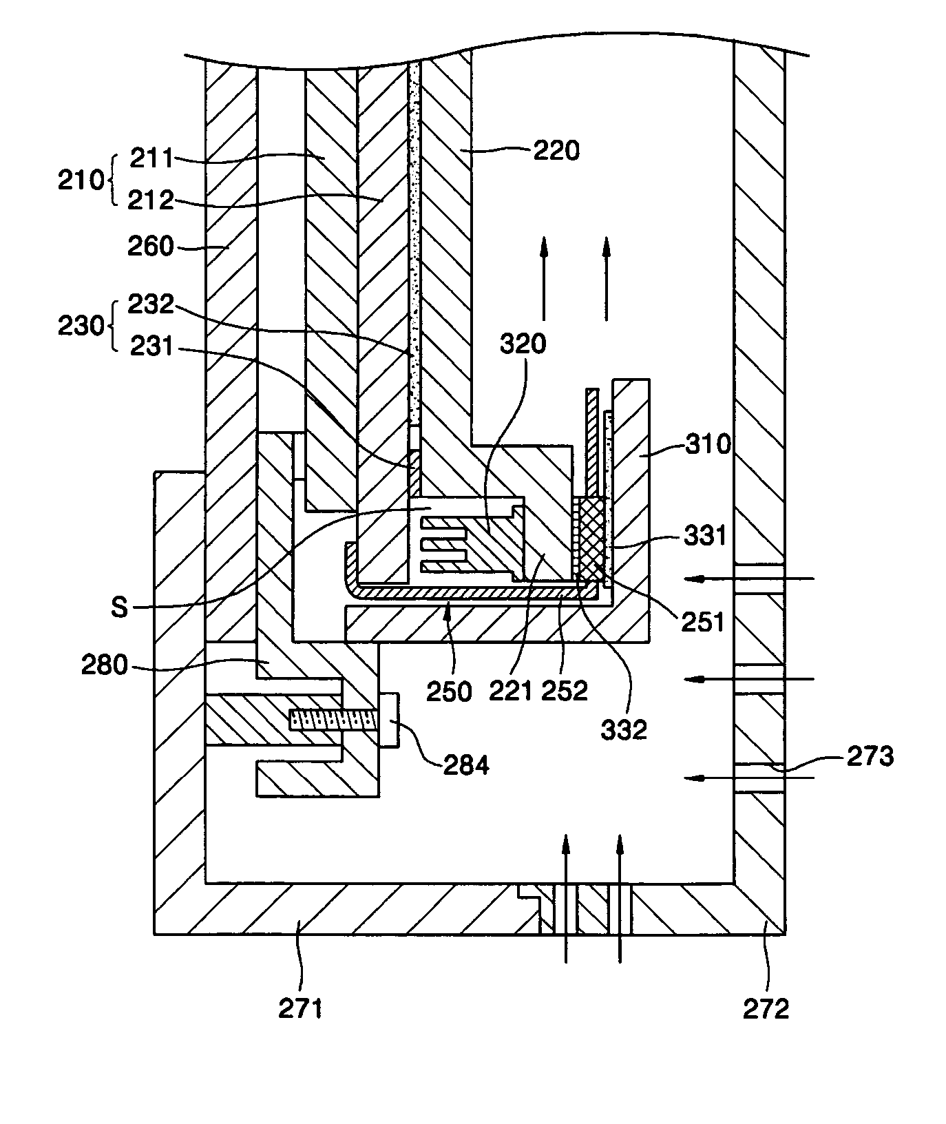
[0043]FIG. 3 is a cross-sectional view of a portion of a PDP assembly in which a heat radiator is mounted according to the present invention. Like reference numerals in the previous drawing denote like elements.
[0044] Referring to FIG. 3, the filter assembly 260, the panel assembly 210, and the chassis base 220 are arranged sequentially in the case 270. That is, the front cabinet 271 is disposed in front of the filter assembly 260, the back cover 272 is disposed at the rear of the chassis base 220, and the filter assembly 260, the panel assembly 210, and the chassis base 220 are disposed in a space formed by joining the front cabinet 271 to the back cover 272.
[0045] The chassis base 220 is attached to a back side of the rear panel 212 by the double-sided tape 231 and the heat radiation sheet 232. The chassis base 220 not only supports the panel assembly 210, but also dissipates heat generated by the panel assembly 210 during operation and transmitted through the radiation sheet 232...
second embodiment
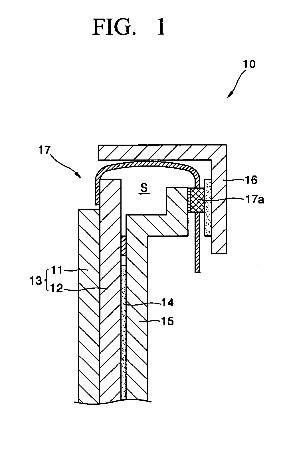
[0056]FIG. 4 is a cross-sectional view illustrating a section of a PDP assembly in which a heat radiator is mounted according to the present invention.
[0057] Referring to FIG. 4, a heat radiator, such as a heat radiation pad 420, is disposed in a space S formed by joining the panel assembly 210, the chassis base 220, and the cover plate 310.
[0058] That is, the heat radiation pad 420 is attached to an inner surface of the end part 221 of the chassis base 220 on which the IC 251 is mounted. The heat radiation pad 420 is preferably formed of a material such as a silicon rubber that can rapidly absorb the heat generated by the IC 251.
[0059] The heat generated by the IC 251 is dissipated through the chassis base 220 and can also be dissipated through the heat radiation pad 420 since the heat radiation pad 420 is mounted on an opposite side of one end 221 of the chassis base 220 on which the IC 251 is mounted.
[0060] As described above, the device according to the present invention can ...
PUM
 Abstract
Description
Claims
Application Information
 - Generate Ideas
- Intellectual Property
- Life Sciences
- Materials
- Tech Scout
- Unparalleled Data Quality
- Higher Quality Content
- 60% Fewer Hallucinations
Browse by: Latest US Patents, China's latest patents, Technical Efficacy Thesaurus, Application Domain, Technology Topic, Popular Technical Reports.
© 2025 PatSnap. All rights reserved.Legal|Privacy policy|Modern Slavery Act Transparency Statement|Sitemap|About US| Contact US: help@patsnap.com