Touch panel and method for manufacturing the same

a technology of resistive film and touch panel, which is applied in the manufacture of electrode systems, electric discharge tubes/lamps, instruments, etc., can solve the problems of poor method for mass production of touch panels, ito films, and large-scale facilities, so as to reduce the cost of manufacturing touch panels, reduce the occurrence of transparent electrode films, and improve mass productivity

Inactive Publication Date: 2005-06-02
FUJITSU COMPONENENT LTD
View PDF9 Cites 94 Cited by
  • Summary
  • Abstract
  • Description
  • Claims
  • Application Information

AI Technical Summary

Benefits of technology

[0031] According to the present invention, in a resistive-film type touch panel, a solution having a transparent conductive polymer dispersed in a solvent is applied to the surface of a substrate and then dried in order to form a transparent electrode film. A special transparent electrode film formation apparatus, such as a sputtering or deposition apparatus, is not needed. A simple technique that does not require alignment, such as screen printing, is adopted as a technique for applying the solution. This results in a reduction in the cost of manufacture of a touch panel.
[0032] Furthermore, as a transparent electrode film is formed using a transparent conductive polymer, occurrence of a damage in the transparent electrode film can be minimized. Consequently, a substrate on which a transparent electrode film is formed is not necessarily hard. Nevertheless, the capability of a touch panel can be fully exerted. Therefore, a transparent resin sheet can be adopted as a substrate. This leads to improved mass productivity and a reduced cos

Problems solved by technology

Therefore, even for production of transparent electrode films for touch panels, a large-scale facility is necessary.
Consequently, the method is poor for the mass production of a touch panel.
Moreover, the ITO film or any other thin film made of a metal oxide that has been adopted as transparent electrode films in the past lacks flexibility and is therefore so susceptible, under bending or an impact, to crack easily.
Therefore, when the thin film is employed in a touch panel, if a pen point or a fingertip is strongly pressed against

Method used


Image

  • Touch panel and method for manufacturing the same
  • Touch panel and method for manufacturing the same
  • Touch panel and method for manufacturing the same

Examples


first embodiment

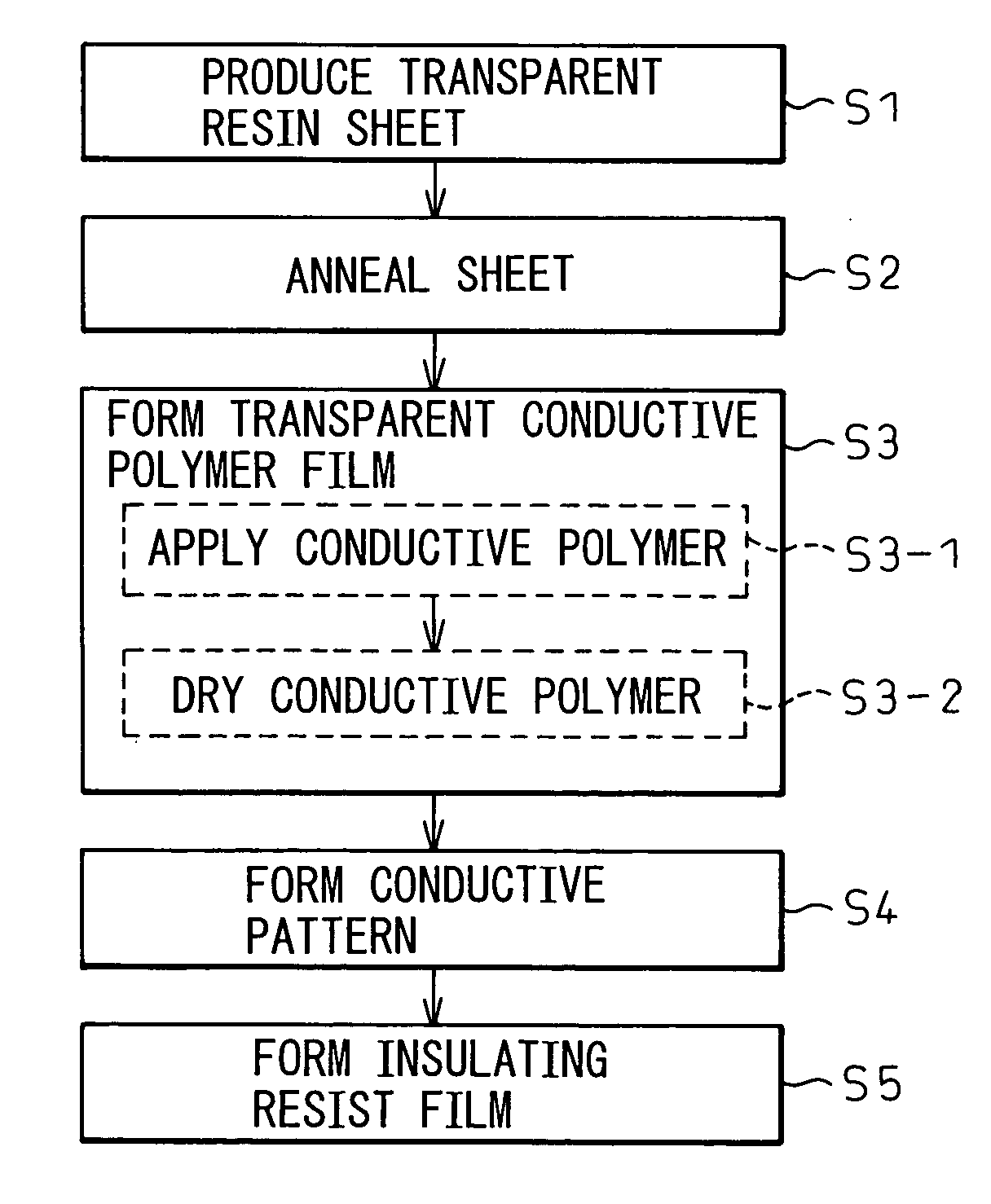
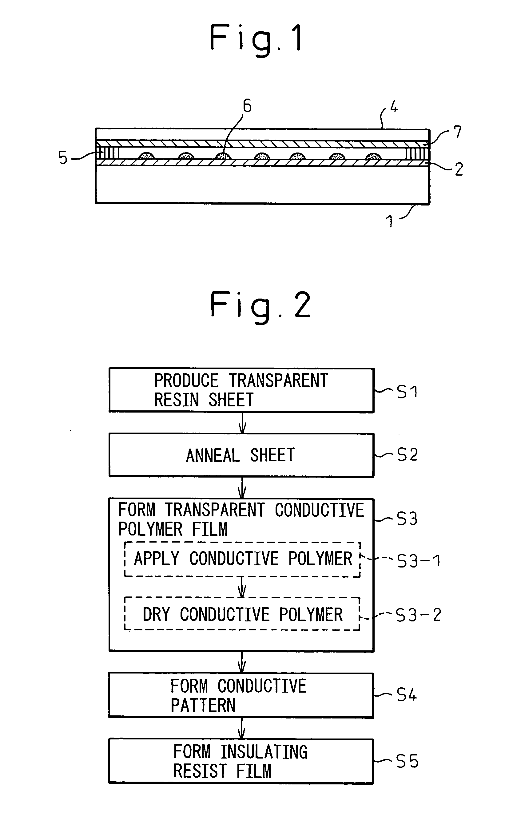
[0060]FIG. 1 is a sectional view of a resistive-film type touch panel in accordance with the first embodiment of the present invention. The first embodiment to be described below adopts as an upper substrate a transparent resin sheet coated with a transparent conductive polymer. The fundamental structure of the resistive-film type touch panel shown in FIG. 1 is identical to that of the resistive-film type touch panel shown in FIG. 17. The same reference numerals are assigned to identical components. The structure of the touch panel in accordance with the first embodiment is different from the structure of the conventional touch panel shown in FIG. 17 in a point that although a transparent electrode film formed on the undersurface of the transparent resin sheet 4 included in the conventional touch panel is made from the ITO film 3, the transparent electrode film included in the touch panel in accordance with the first embodiment is made from a transparent conductive polymer film 7 bu...

second embodiment

[0081] In the resistive-film type touch panel in accordance with the first embodiment, a glass substrate is adopted as a lower substrate. In the second embodiment, a transparent resin sheet adopted as an upper substrate is also adopted as a lower substrate so that an entire touch panel will be flexible. The touch panel can be installed while being curved. Thus, the usefulness of the touch panel is intensified, the mass productivity thereof is improved, and the cost of manufacture is reduced.

[0082]FIG. 6 shows the structure of a resistive-film type touch panel in accordance with the second embodiment. In the structure, similarly to the structure of the resistive-film type touch panel shown in FIG. 5, transparent conductive polymer films 7 and 8 are adopted as transparent electrode films formed on upper and lower substrates respectively. However, a transparent resin sheet 9 is adopted as the lower substrate on behalf of a glass substrate 1. Consequently, the same substrate can be use...

third embodiment

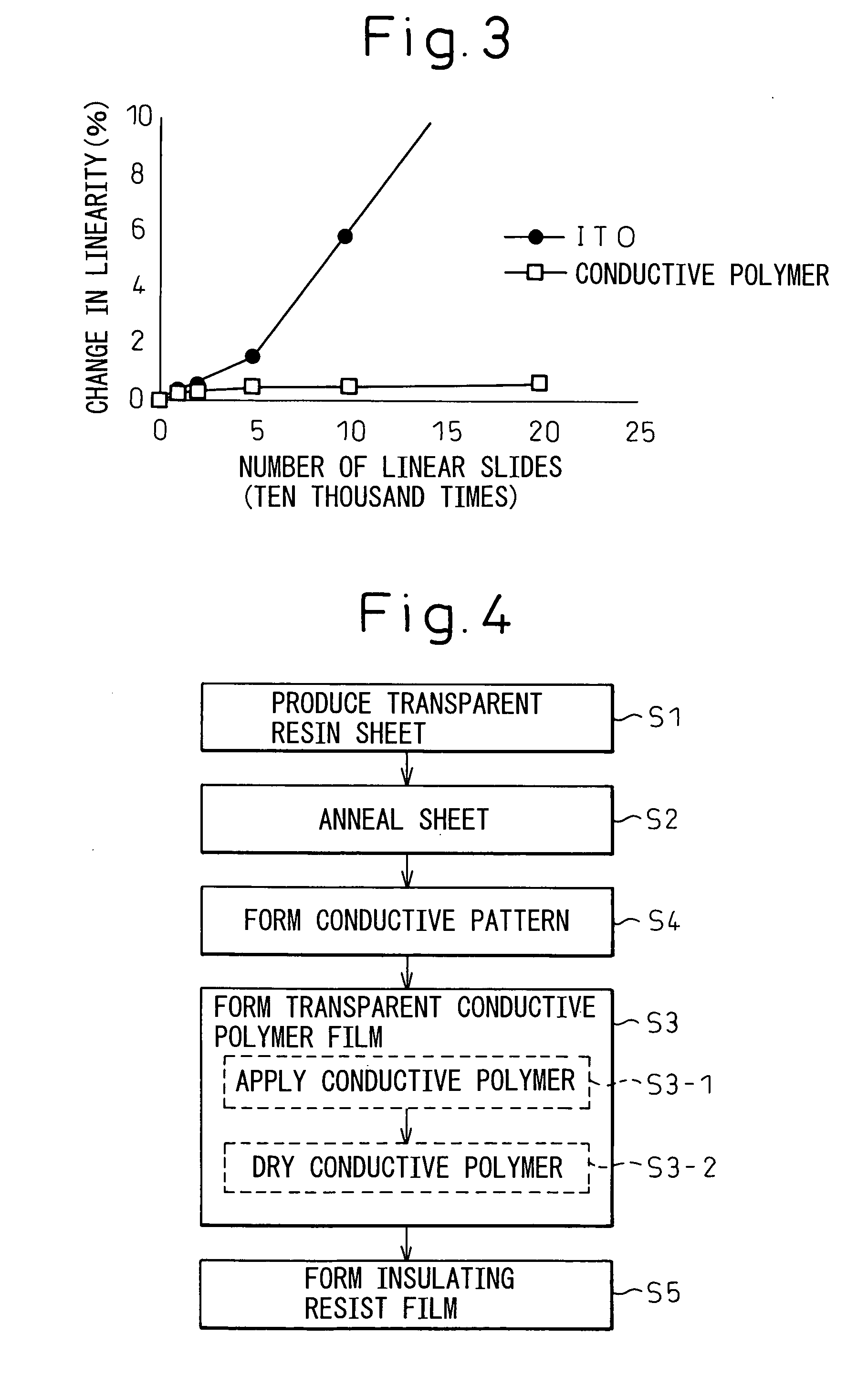
[0095] A third embodiment is a resistive-film type touch panel in which a transparent resin sheet produced by laminating an ITO film and a transparent conductive polymer is adopted as a transparent electrode film. The fact that a conductive polymer film produced by applying a solution of a transparent conductive polymer and drying the solution is superior in sliding smoothness has been described in conjunction with FIG. 3. The third embodiment utilizes the fact that a transparent conductive film is made of a polymer in an effort to suppress degradation of the linearity in a touch panel occurring when an ITO film is adopted as a transparent electrode film.

[0096]FIG. 9 is a sectional view showing the structure of a resistive-film type touch panel in accordance with the third embodiment. The resistive-film type touch panel shown in FIG. 9 is based on the conventionally adopted resistive-film type touch panel shown in FIG. 17. The same reference numerals are assigned to identical compo...


PUM


Abstract

The present invention relates to a resistive-film type touch panel using a transparent conductive polymer film as a transparent electrode film. The touch panel includes a transparent resin sheet and a glass substrate having an ITO film formed thereon. After a solution having a transparent conductive polymer dispersed in a solvent is applied to the undersurface of the transparent resin sheet, the solution is heated and dried in order to form a transparent conductive polymer film. The ITO film and transparent conductive polymer film serve as transparent electrode films that are opposed to each other. When the transparent resin sheet is pressed, the films touch each other. Consequently, a change in resistance corresponding to the pressed position can be detected.

Description

CROSS-REFERENCE TO RELATED APPLICATIONS [0001] This application claims the priorities of Japanese Patent Application No. 2003-397285, filed on Nov. 27, 2003, and of Japanese Patent Application No. 2004-121702, filed on Apr. 16, 2004. BACKGROUND OF THE INVENTION [0002] 1. Field of the Invention [0003] The present invention relates to a resistive-film type touch panel that can detect a change in resistance corresponding to a pressed position and a method for manufacturing the touch panel. More particularly, the present invention is concerned with a resistive-film type touch panel that does not require large manufacturing equipment but makes it possible to adopt a simple technique of forming an electrode film so as to reduce the cost of manufacture, and a method of manufacturing the touch panel. [0004] 2. Description of the Related Art [0005] Conventionally, touch panels are mounted on the screens of a cathode-ray tube serving as a display device, a flat-panel display connected to a pe...

Claims


Application Information

Patent Timeline
IPC IPC(8): G06F3/045G06F3/03G06F3/041H01H1/06H01J9/00H01J9/24
CPCG06F3/045G06F2203/04104G06F2203/04103
Inventor ENDO, MICHIKO
Owner FUJITSU COMPONENENT LTD
Why Eureka
Try Eureka