Disk array system and method for controlling disk array system

a technology of disk array system and array system, which is applied in the direction of digital signal error detection/correction, instruments, recording signal processing, etc., can solve the problems of serial ata or parallel ata hard disk drives being inferior in reliability to fiber channel hard disk drives, increasing the unit cost of manufacturing each hard disk drive, and reducing the pri

Inactive Publication Date: 2005-06-02
HITACHI LTD
View PDF98 Cites 52 Cited by
  • Summary
  • Abstract
  • Description
  • Claims
  • Application Information

AI Technical Summary

Benefits of technology

[0011] Here, the first interface standard is, for example, a fiber channel standard. The second interface standard is, for example, a serial ATA standard. The communication path is, for example, an FC-AL (Fiber Channel-Arbitrated Loop). In addition, each converting unit is, for example, a converter for converting a fiber channel protocol and a serial ATA protocol into each other. In addition, each RAID group is to manage a plurality of hard disk drives as one group when the

Problems solved by technology

Thus, the unit cost for manufacturing each hard disk drive increases.
This is because serial ATA or parallel

Method used


Image

  • Disk array system and method for controlling disk array system
  • Disk array system and method for controlling disk array system
  • Disk array system and method for controlling disk array system

Examples


Embodiment Construction

System Configuration

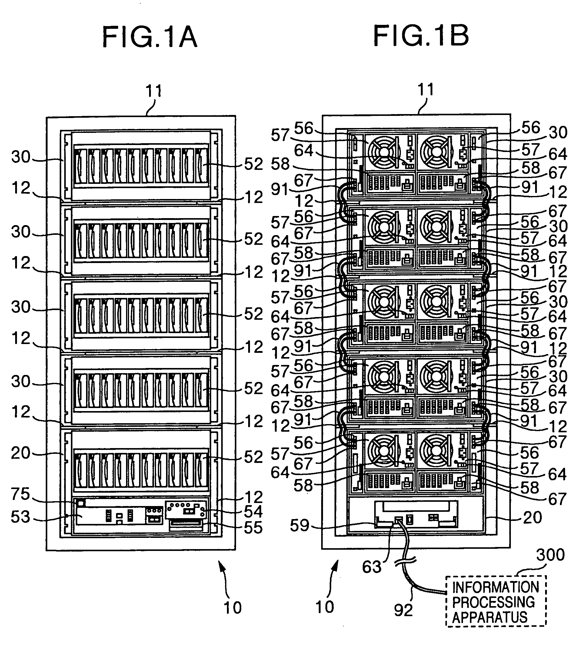
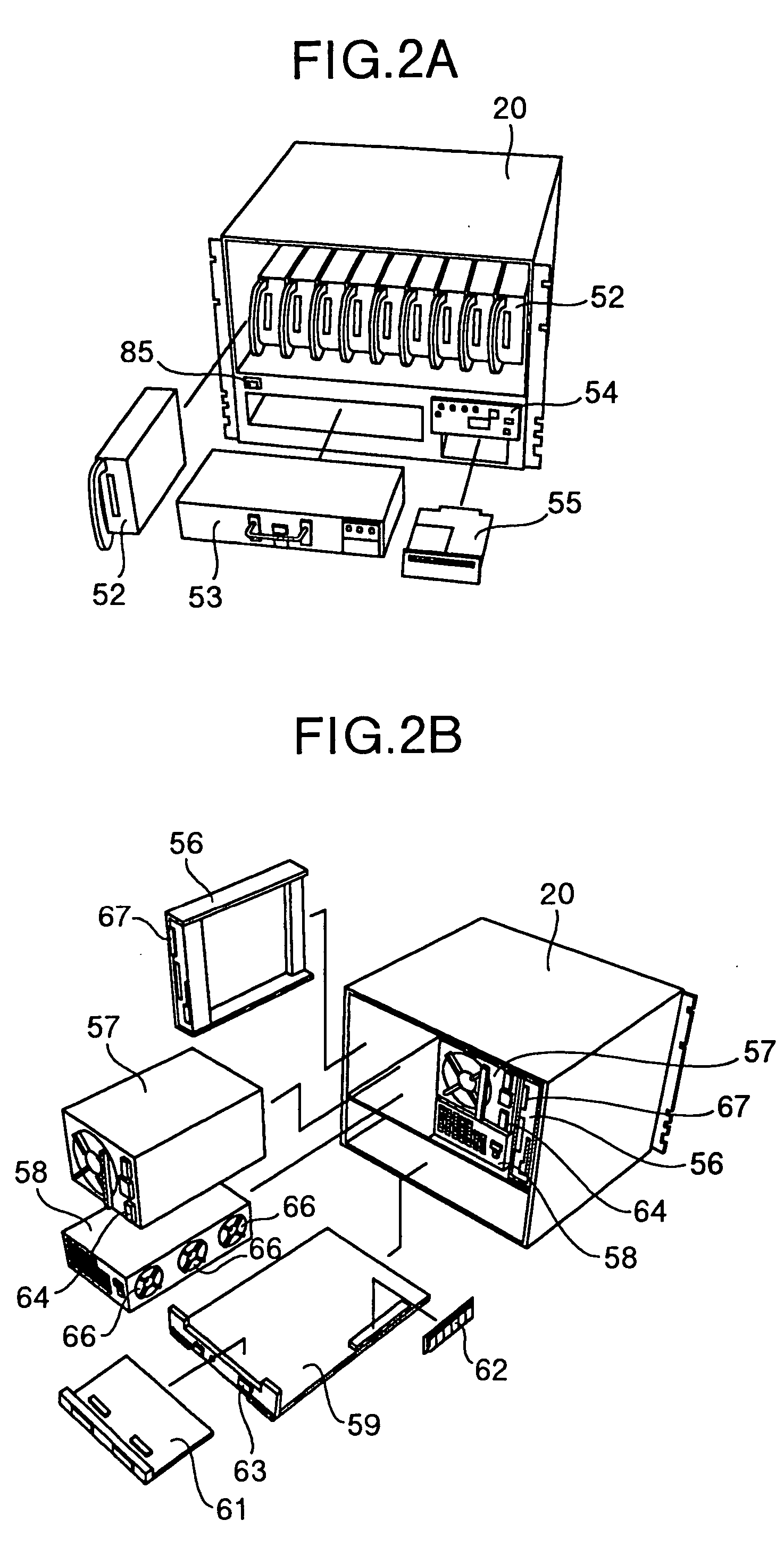
[0035]FIG. 1A is a front view of a disk array system 10 which will be described as an embodiment of the invention. FIG. 1B is a back view of the disk array system 10. FIG. 2A is a perspective view of a master housing 20 to be mounted on the disk array system 10, the master housing 20 being viewed from its front side. FIG. 2B is a perspective view of the master housing 20 viewed from its back side. FIG. 3A is a perspective view of an expansion housing 30 to be mounted on the disk array system 10, the expansion housing 30 being viewed from its front side. FIG. 3B is a perspective view of the expansion housing 30 viewed from its back side.

[0036] As shown in FIGS. 1A and 1B, the disk array system 10 is formed by using a rack frame 11 as a base. Mount frames 12 are formed in a plurality of stages disposed in the upper and lower on the inside left and right side surfaces of the rack frame 11, so as to extend in the front / rear direction. The master housing 20 and exp...


PUM


Abstract

A disk array system having first and second housings and a controller for controlling the first and second housings. Fiber channel hard disk drives are received in the first housing, and serial ATA hard disk drives are received in the second housing. When reading data stored in a serial ATA hard disk drive in the second housing, the controller reads a plurality of pieces of data including the data to be read and parity data for the plurality of pieces of data from all the hard disk drives of an RAID group to which the hard disk drive storing the data to be read belongs. Thus, the controller examines whether the plurality of pieces of data including the data to be read are written in the hard disk drives with erroneous contents or not.

Description

[0001] The present application is a continuation of application Ser. No. 10 / 766,015, filed Jan. 29, 2004, the contents of which are incorporated herein by reference.BACKGROUND OF THE INVENTION [0002] The present invention relates to a disk array system and a method for controlling a disk array system. [0003] In recent years, with the increase of storage capacity in disk array systems, the importance thereof in information processing systems becomes greater and greater. It is therefore essential to write data correctly in a requested position and detect falseness in read data in response to a data input / output request from an information processing apparatus or the like. [0004] JP-A-5-150909 discloses a method in which two heads are provided in a magnetic disk unit, and identical data read from the two heads are compared with each other so as to enhance the reliability in writing and reading in the magnetic disk unit. [0005] When the method disclosed in JP-A-5-150909 is applied to a ...

Claims


Application Information

Patent Timeline
IPC IPC(8): G06F11/00G06F3/06G06F11/10G06F11/14G06F12/16G06F13/38G11B5/012G11B7/085G11B20/18G11B33/14G11C7/00
CPCG06F3/0614G06F3/0659G06F3/0665G11B20/18G06F11/1076G06F12/0866G06F3/0689G06F3/06G06F13/382G11B20/1816G11B20/1879G06F11/10
Inventor KANO, AZUMAOGAWA, TAKUJIYAGISAWA, IKUYA
Owner HITACHI LTD
Why Eureka
Try Eureka