Kneepad having adjustable sizing pieces

a technology of adjustable sizing and knee pads, which is applied in the field of knee pads having adjustable sizing, can solve the problems of inability to comfortably use the same kneepad by different users with different knee sizes, and the protective portion of the kneepad often does not securely fit against the knee of a user

Inactive Publication Date: 2005-06-09
BLACK & DECKER INC
View PDF57 Cites 7 Cited by
  • Summary
  • Abstract
  • Description
  • Claims
  • Application Information

AI Technical Summary

Benefits of technology

[0005] In one aspect of the invention, a kneepad includes a base defining an interior side and a sizing piece attached to the interior side of the base. Moving the sizing piece relative to the base determines the size of a knee that can be accommodated by the kneepad. To accommodate a large knee, the sizing pieces may be rotated away from the center of the interior side of the base. To accommodate a small knee, the sizing pieces may be rotated towards the center of the interior side of the base.

Problems solved by technology

These traditional protective kneepads, however, suffer from a number of deficiencies.
Furthermore, as the size of any one kneepad is typically static and not adjustable, the same kneepad cannot be used comfortably by different users with different sized knees.
Therefore, the protective portion of the kneepad often does not securely fit against the knee of a user and tends to rotate about the knee or move off of the front of the knee.
This movement can cause irritation to the leg and knee of the user due to rubbing.
It can also cause problems when the protective area of the kneepad no longer protects the knee of the user, thereby defeating the purpose of the kneepad.

Method used


Image

  • Kneepad having adjustable sizing pieces
  • Kneepad having adjustable sizing pieces
  • Kneepad having adjustable sizing pieces

Examples


first embodiment

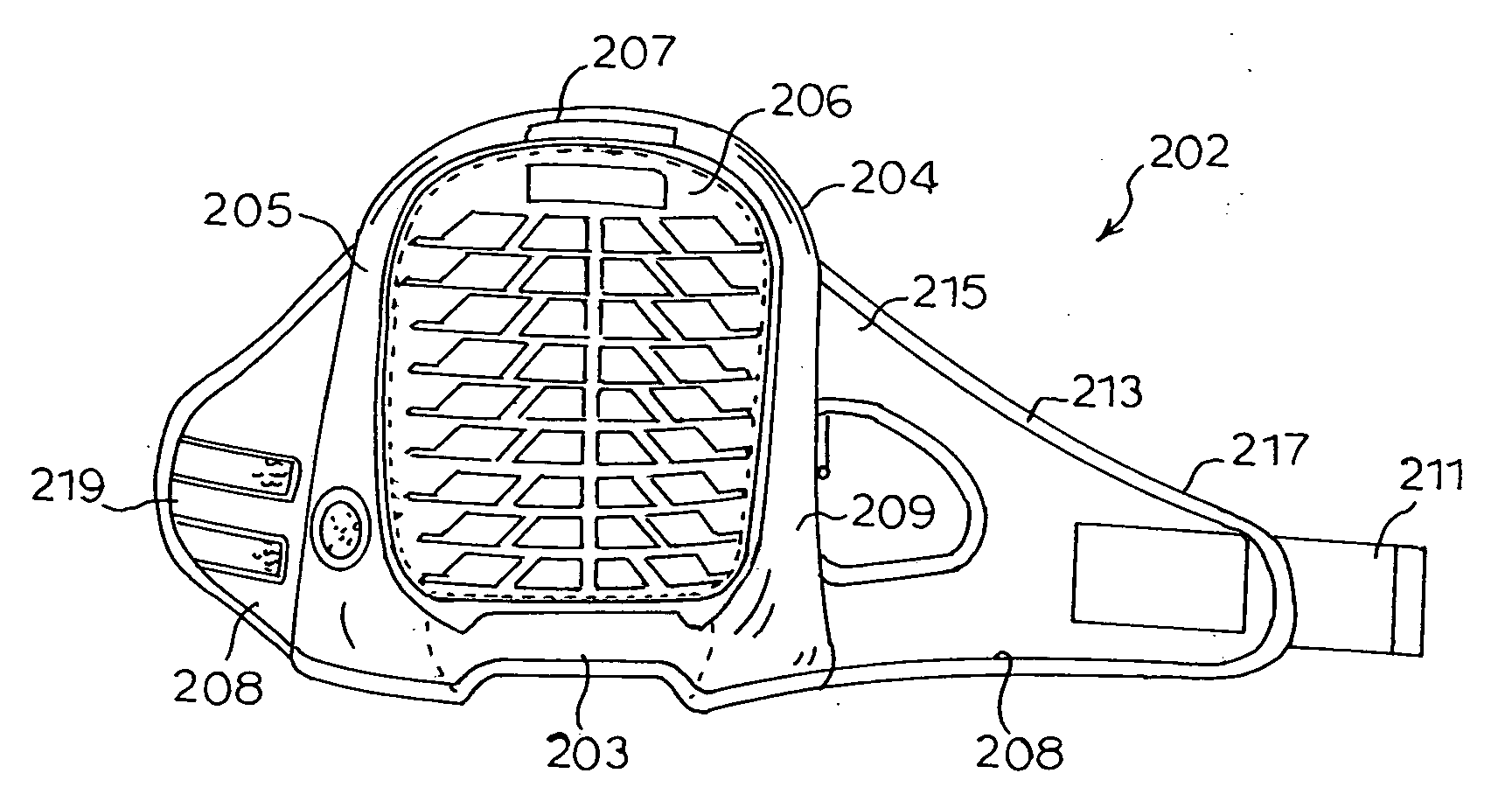
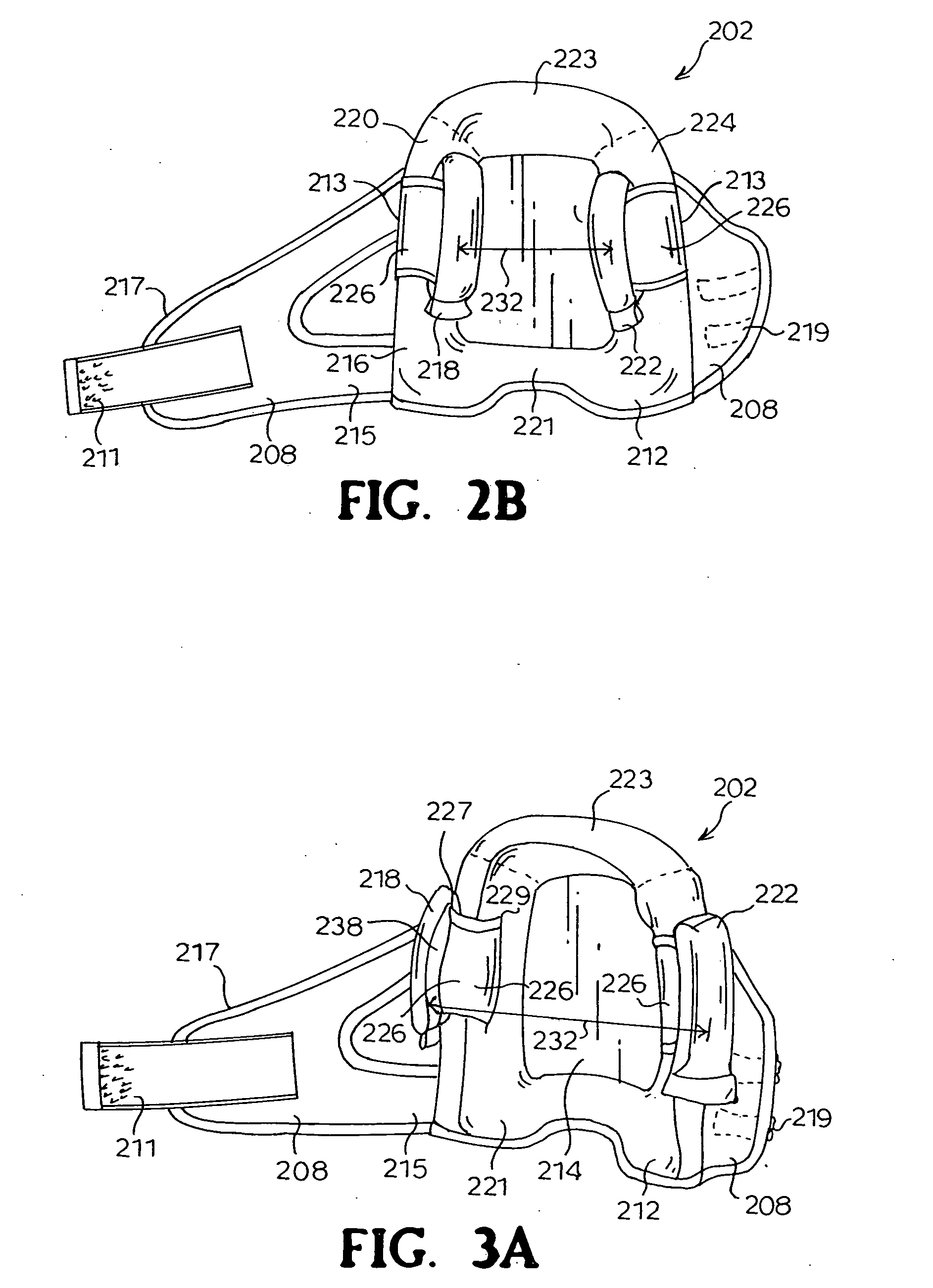
[0022] In a first embodiment shown in FIGS. 1-3, each of the sizing pieces 218, 222 is rotatably attached to the kneepad 202 to rotate about the first or second interior walls 220, 224 by slidably attaching each sizing piece 218, 222 to a separate strap 226, each of which partially surrounds one of the side walls 216 of the concave region 214. Typically, a first end 229 of the strap 226 is attached to the flexible base 204 on a first side 233 of the side wall 216 of the concave region 213 and a second end 216 of the strap 226 is attached to the flexible base 204 on a second side of the side wall 216 of the concave region 214.

[0023] Each sizing piece218, 222 typically includes a loop 227 on an interior side 238 of the sizing piece 218, 222. The strap 226 passes through the loop 227 to allow the strap 226 to guide the movement of the sizing piece 218, 222 such that the sizing piece 218, 222 may be slidably attached to the strap 226 and rotate towards the center of the concave region 2...

second embodiment

[0026] In a second embodiment shown in FIGS. 4 and 5, the sizing pieces 418, 422 are rotatably attached to the first and second interior walls 420, 424 by attaching each sizing piece 418, 422 to a circular piece of elastomeric material 430. The circular piece of elastomeric material 430 surrounds one of the side walls 416 and passes through an opening 437 below the side wall 416 on the flexible base 404 such that the elastomeric material may rotate around the side wall 416 of the concave region 414.

[0027] During use, rotating a sizing piece 410 away from or towards the center of the concave region 414 is achieved by rotating the piece of elastomeric material 430 around the side wall 416, thereby rotating the sizing piece 410. To hold the sizing piece 410 in a desired position along the side wall 416 of the concave region 414, a kneepad could utilize friction, a hoop and look fastener, or any other type of system known in the art.

[0028] In some embodiments, the piece of elastomeric ...


PUM


Abstract

A kneepad comprises a base defining an interior side and a sizing piece attached to the interior side of the base. Moving the sizing piece relative to the base determines the size of a knee that can be accommodated by the kneepad. To accommodate a large knee, the sizing piece may be rotated away from the center of the interior side of the base. To accommodate a small knee, the sizing piece may be rotated towards the center of the interior side of the base.

Description

RELATED APPLICATIONS [0001] The present patent document claims the benefit of the filing date under 35 U.S.C. §119(e) of Provisional U.S. Patent Application Ser. No. 60 / 527,851, filed Dec. 8, 2003, the entire contents of which is hereby incorporated by reference.BACKGROUND [0002] Historically, to prevent knee injuries during physical activity that requires being in a kneeling position, a user would wear a protective kneepad over the front of their knee. Traditional protective kneepads normally include some type of rigid cap secured against the front of a knee by some type of strap that surrounds the knee and leg of the user. [0003] These traditional protective kneepads, however, suffer from a number of deficiencies. For example, typical kneepads only come in one size or a limited number of sizes. Furthermore, as the size of any one kneepad is typically static and not adjustable, the same kneepad cannot be used comfortably by different users with different sized knees. Therefore, the...

Claims


Application Information

Patent Timeline
Patent Type & Authority Applications(United States)
IPC IPC(8): A41D13/00A41D13/06
CPCA41D13/065A41D13/0568
Inventor CUNNINGHAM, IAN W.
Owner BLACK & DECKER INC
Why Eureka
Try Eureka