
Must clarification machine

a technology of a clarification machine and a cylinder, which is applied in the direction of biochemistry apparatus and processes, water/sludge/sewage treatment, food shaping, etc., can solve the problems of adversely affecting the vinification process, the clarification is not homogeneous, and the subsequent process is affected

Inactive Publication Date: 2009-07-07
INOXPA
View PDF7 Cites 1 Cited by
  • Summary
  • Abstract
  • Description
  • Claims
  • Application Information

AI Technical Summary

Benefits of technology

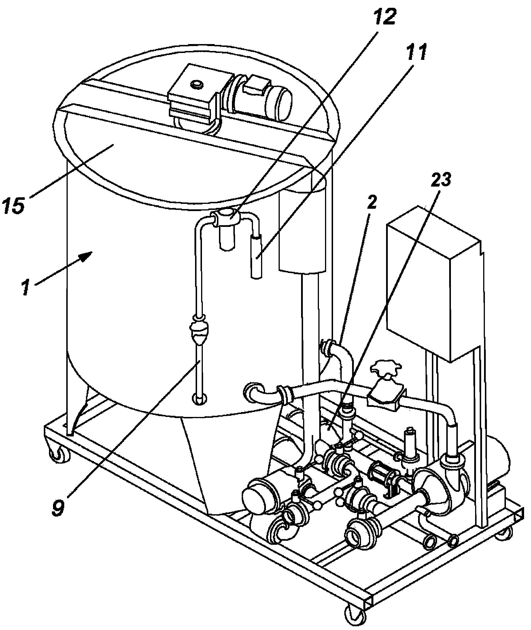
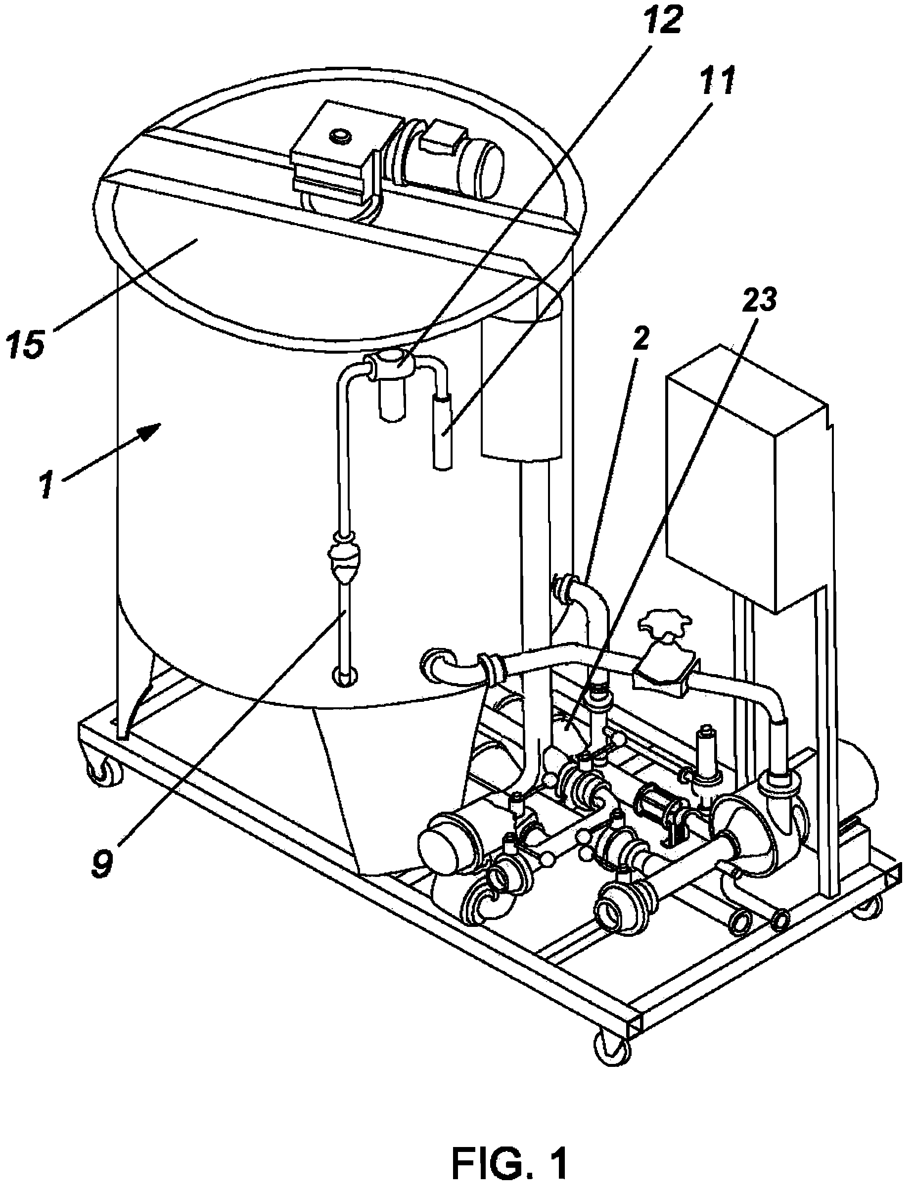
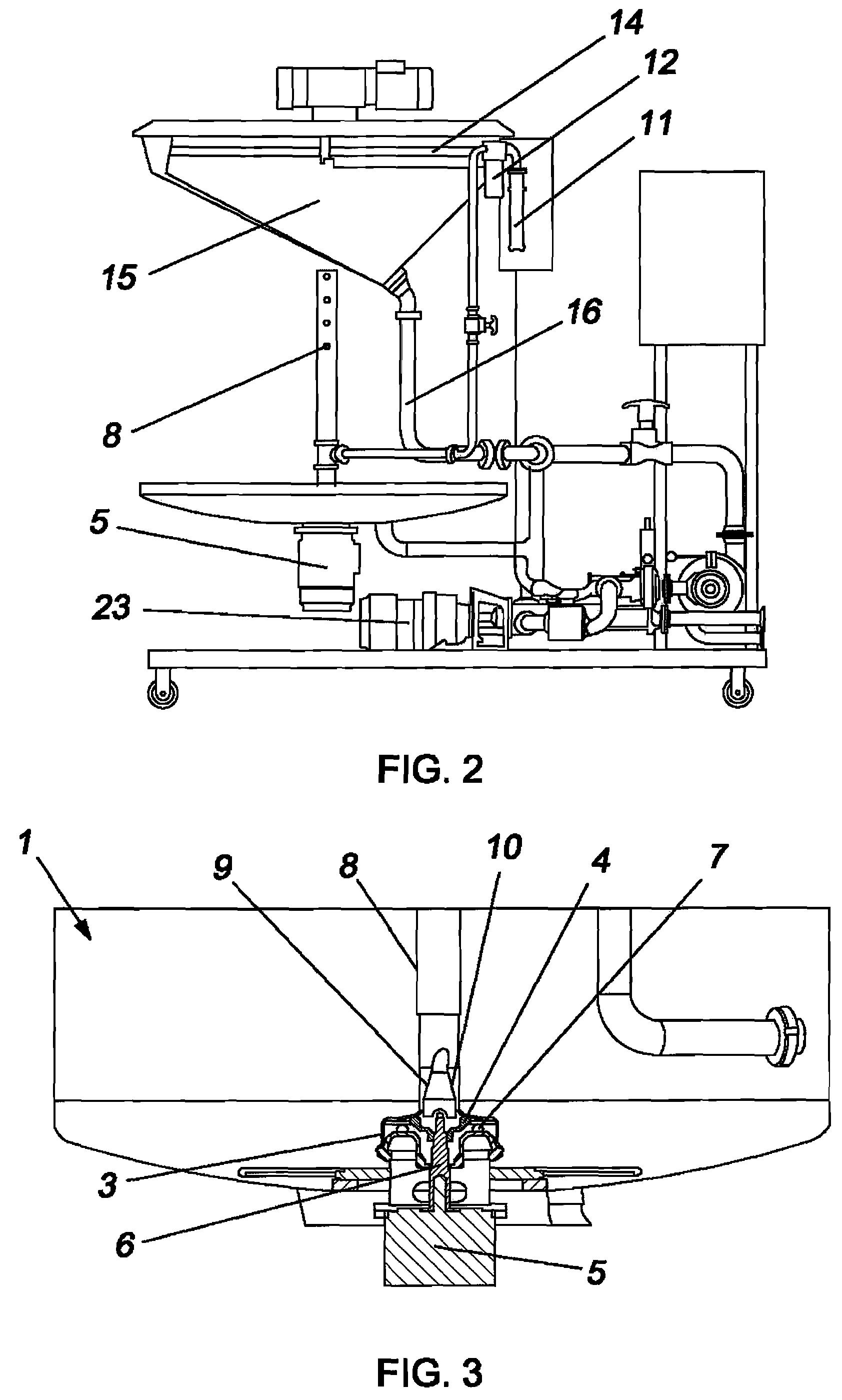
"The invention is a machine for clarifying must, such as grapes, to obtain quality wines. The machine uses air bubbles to remove impurities and sediment from the must. The invention includes a flotation vat with a turbine and a circular chamber for injecting air and mixing it with the must. The air is injected through a hole at the top of the chamber, which creates a depression to suck ambient air through the inner pipe. The machine ensures a continuous and homogeneous distribution of air bubbles throughout the must. The technical effect of the invention is to provide a more efficient and effective means of clarifying musts in the winemaking process."

Problems solved by technology

The presence of deposits or impurities in the must obtained after pressing the fruit leads to problems in the subsequent processes, such as fermentation in the case of grapes.
These impurities, besides producing undesirable vegetable aromas, cause the yeast to precipitate, leaving its sediment on the bottom of the fermentation vat, which adversely affects the vinification process.
Apart from the increase in power consumption implied by this compressor unit, the air injection is produced locally in the application points, and the clarification is therefore not homogeneous.
The drawback of this apparatus is that the aeration is produced in a very localised manner in the application point, that is, in the vicinity of the helical coil, not ensuring the aeration to the most distant points.

Method used


Image

  • Must clarification machine
  • Must clarification machine
  • Must clarification machine

Examples


Embodiment Construction

[0012]The machine for continuous and batch must clarification proposed by the invention solves the aforementioned problems, as it includes means to ensure that the dispersion of air bubbles is homogeneous and continuous, throughout the whole volume of must contained in the flotation vat.

[0013]For this purpose, and more specifically, the must clarification machine is of the type comprising a flotation vat in which must obtained from fruit pressing, particularly grapes, is introduced through a channel driven by a pump, provided with means for injecting air and making the impurities contained in the must float.

[0014]Said means comprise a circular chamber placed in the centre of the internal base of the vat, inside which a turbine actuated by a motor rotates and sucks the must contained in the flotation vat, mixing it with the air, and expelling it through holes on the sides of the circular chamber, having ensured that the must and air admission is through a hole at the top of the chamb...


PUM

PropertyMeasurementUnit
centrifugal forceaaaaaaaaaa
volumesaaaaaaaaaa
vacuumaaaaaaaaaa

Abstract

A must clarification device is provided comprising a vat into which the must is introduced in either a continuous flow or in batches. Located within a circular chamber in the vat is a turbine rotatable by external means. The must is introduced into the chamber by a centrally located pipe. An air pipe is located concentrically within the must pipe. The pipes are arranged to create a venturi effect to suck the air into the chamber. The turbine mixes the air and must and expells it from the chamber so that the air bubbles cause the impurities to rise to the surface where they are removed.

Description

[0001]This application claims the benefit of Spanish Application No. 200603168, filed on Dec. 14, 2006, the entire disclosure of which is incorporated by reference.OBJECT OF THE INVENTION[0002]This invention relates to a machine for clarification, both as a continuous process and a batch process, of the must obtained after pressing the fruit, particularly grapes, which is the stage prior to obtaining the juice from the fruit, or fermenting it to obtain wine.[0003]The object of this invention focuses on implementing means of injecting air bubbles into the must to cause the must deposits or impurities to float in order to withdraw them and clarify the must.BACKGROUND OF THE INVENTION[0004]In traditional white- and rosé-wine vinification, thermovinification of red wine, as well as other more specific types of vinification, the must-cleansing process, known as clarification, is a key step in obtaining quality wines.[0005]The presence of deposits or impurities in the must obtained after ...

Claims


Application Information

Patent Timeline
Patent Type & Authority Patents(United States)
IPC IPC(8): C02F1/24
CPCC12G1/02A23L2/82B03D1/14
Inventor WAIDELICH, GUNTER
Owner INOXPA
Learn More